
Integrated motor driving system

A motor drive system and motor shaft technology, applied in control devices, transportation and packaging, vehicle parts, etc., can solve the problems of large space occupation, increased drive system volume, low power density, etc., to reduce occupied space, solve Layout design, the effect of increasing transmission efficiency

Active Publication Date: 2012-03-14
SAIC MOTOR
View PDF5 Cites 18 Cited by
  • Summary
  • Abstract
  • Description
  • Claims
  • Application Information

AI Technical Summary

Problems solved by technology

The research and development of new energy vehicles, including fuel cell electric vehicles, gasoline-electric hybrid vehicles, solar electric vehicles, and pure electric vehicles, has brought hope to the solution of this problem. However, since the new power sources are mainly power batteries and motor drives The transmission system has low power density and takes up a lot of space, making the layout of the power system a difficult point for new energy vehicles
[0003] In order to solve the layout problem in the limited space of the power system, the integrated integration of the power system is the key. At present, the drive system in the new energy power system mostly adopts a parallel shaft output structure. This structure is simple to implement and mature in technology, but its size is large. Difficult to arrange
Patent CN101204924A discloses an electric vehicle drive system integrated with a motor and a two-speed fixed speed ratio reducer. Through clutch control, two-speed speed change can be realized, but the integration of differential mechanism is not realized, and two-speed speed change is easy to cause gear shifting shock
Patent CN101204925A discloses another electric vehicle drive system. Although the system uses dual-clutch technology to reduce the impact of shifting and increase the smoothness of shifting, the use of dual-clutch technology for the speed reduction mechanism of only two gears not only makes the manufacturing The serious increase in cost also brings the complexity of the structure of the drive system itself, increases the volume of the drive system, and in turn has a certain impact on the layout of the vehicle

Method used


Image

  • Integrated motor driving system
  • Integrated motor driving system
  • Integrated motor driving system

Examples


Embodiment Construction

[0020] Preferred embodiments of the present invention will be described in detail below in conjunction with the accompanying drawings.

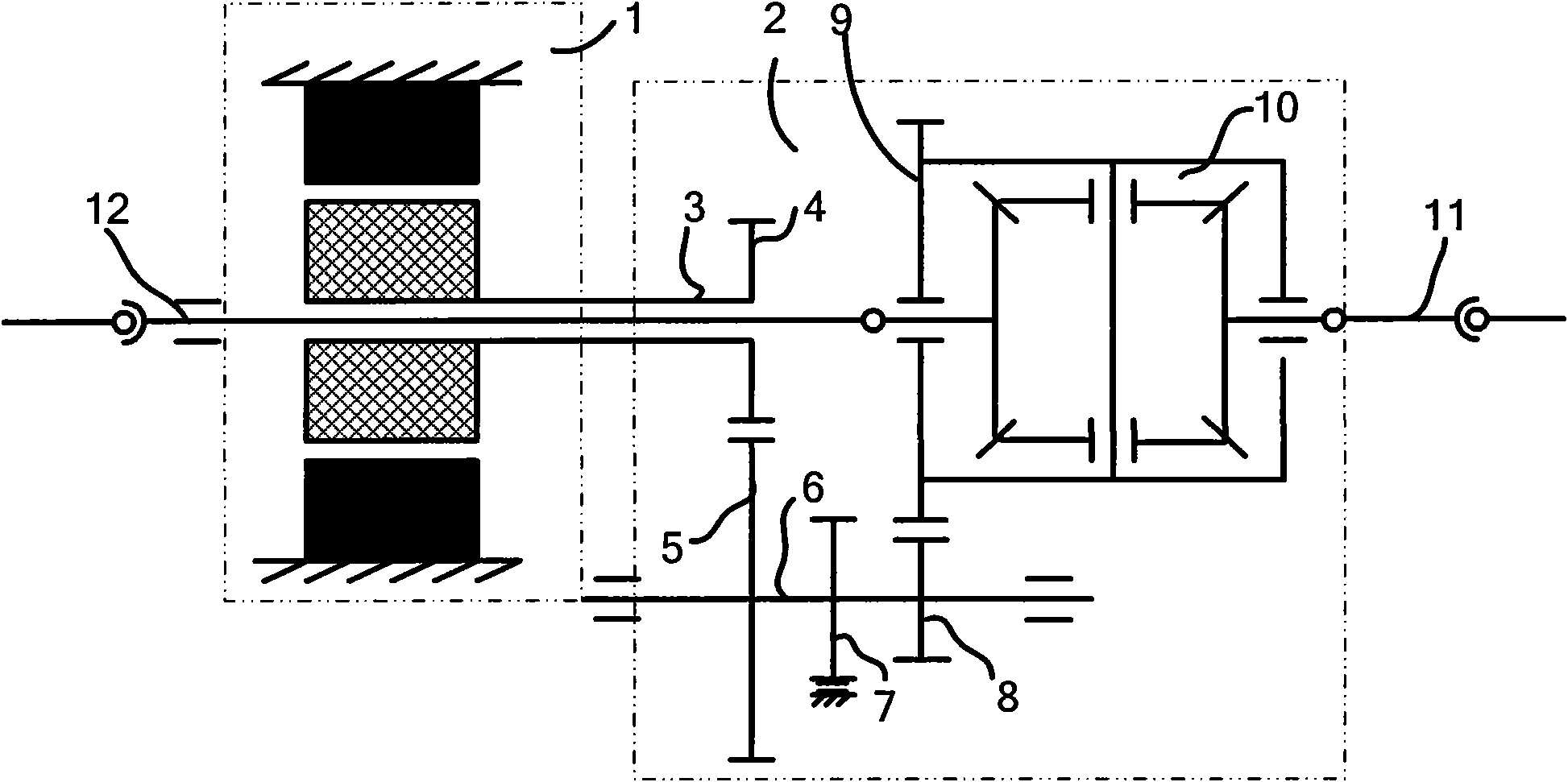
[0021] Such as figure 1 As shown, the integrated motor drive system includes a motor 1 , a reducer 2 , a differential 10 , a parking mechanism 7 and two transmission shafts 11 , 12 . The rotor of the motor 1 is supported on the casing by a pair of grease lubricated grooved ball bearings, and the motor shaft 3 connected with the rotor is a hollow shaft. The reducer 2 includes a primary gear set and a secondary gear set. The primary gear set includes a driving gear 4 and a driven gear 5. The driving gear 4 meshes with the driven gear 5. The secondary gear set includes a driving gear 8 and a passive gear 9. The gear 8 meshes with the driven gear 9, the driven gear 5 of the primary gear set is coaxially connected with the driving gear 8 of the secondary gear set through an intermediate shaft 6, and the parking mechanism 7 is arranged on the inte...


PUM


Abstract

The invention discloses an integrated motor driving system, which comprises a motor, a speed reducer, a differential mechanism and two transmission shafts, wherein a motor shaft of the motor is a hollow shaft; the speed reducer comprises a first-stage gear set and a second-stage gear set; a driving gear of the first-stage gear set is fixed on the motor shaft; a driven gear of the first-stage gear set is coaxially connected to a driving gear of the second-stage gear set by an intermediate shaft; the differential mechanism is connected to a driven gear of the second-stage gear set; the transmission shafts are respectively connected to two output ends of the differential mechanism; one of the transmission shafts passes through the motor shaft and is connected to a hub on one side of a vehicle; and the other transmission shaft is connected to a hub on the other side of the vehicle. A power system of a new-energy vehicle adopting the motor driving system has the advantages of relative compact structure, higher integrated degree and promoted transmission efficiency. The motor driving system is beneficial to the arrangement and design of the power system of the new-energy vehicle.

Description

technical field [0001] The invention relates to a motor drive system, in particular to an integrated motor drive system for new energy vehicles. Background technique [0002] While vehicles bring convenience to people's lives, they also cause serious pollution to the external environment. The spread of global greenhouse gases affects the survival of human beings. Moreover, due to the long-term development of global oil resources, the world's energy has been exhausted. How to save energy and protect the environment has become an urgent task for the automotive industry in the world today. The research and development of new energy vehicles, including fuel cell electric vehicles, gasoline-electric hybrid vehicles, solar electric vehicles, and pure electric vehicles, has brought hope to the solution of this problem. However, since the new power sources are mainly power batteries and motor drives The transmission system has low power density and takes up a lot of space, making t...

Claims


Application Information

Patent Timeline
Patent Type & Authority Applications(China)
IPC IPC(8): B60K17/12B60K17/16
Inventor 欧阳启路华鹏曹建荣程伟税方曹海平陈玮山
Owner SAIC MOTOR
Learn More