
Lorry spiral bevel gear double-row rare earth continuous gas carburization heat treatment equipment

A technology for heat treatment equipment and trucks, applied in coating, metal material coating technology, solid diffusion coating, etc., can solve the problem of poor anti-adhesive wear performance of gears, low surface hardness of carburized gears, and easy blockage of drip tubes To achieve the effect of increasing the carburizing speed, avoiding the out-of-tolerance level of retained austenite, and shortening the pushing cycle

Active Publication Date: 2013-07-10
哈尔滨汇隆汽车箱桥有限公司 +3
View PDF5 Cites 0 Cited by
  • Summary
  • Abstract
  • Description
  • Claims
  • Application Information

AI Technical Summary

Problems solved by technology

[0003] In order to solve the disadvantages of poor carburized layer uniformity of carburized gear parts in the existing production line and the temperature of V-zone parts being higher than the quenching temperature, resulting in thick martensite needles and out-of-tolerance grades of residual austenite, carbon black is easily produced , the amount of methanol used is large, the cost of carburizing is high; the hardness of the carburized gear surface is low, the performance of the gear against adhesive wear is poor, the service life of the spiral bevel gear produced is short, the failure rate of the equipment is high, and the drip tube is easy to block To solve the problem, a double-row rare earth continuous gas carburizing heat treatment equipment for the spiral bevel gear of the truck is provided. The specific technical solution to solve the problem is as follows:

Method used


Image

  • Lorry spiral bevel gear double-row rare earth continuous gas carburization heat treatment equipment
  • Lorry spiral bevel gear double-row rare earth continuous gas carburization heat treatment equipment
  • Lorry spiral bevel gear double-row rare earth continuous gas carburization heat treatment equipment

Examples


specific Embodiment approach 1

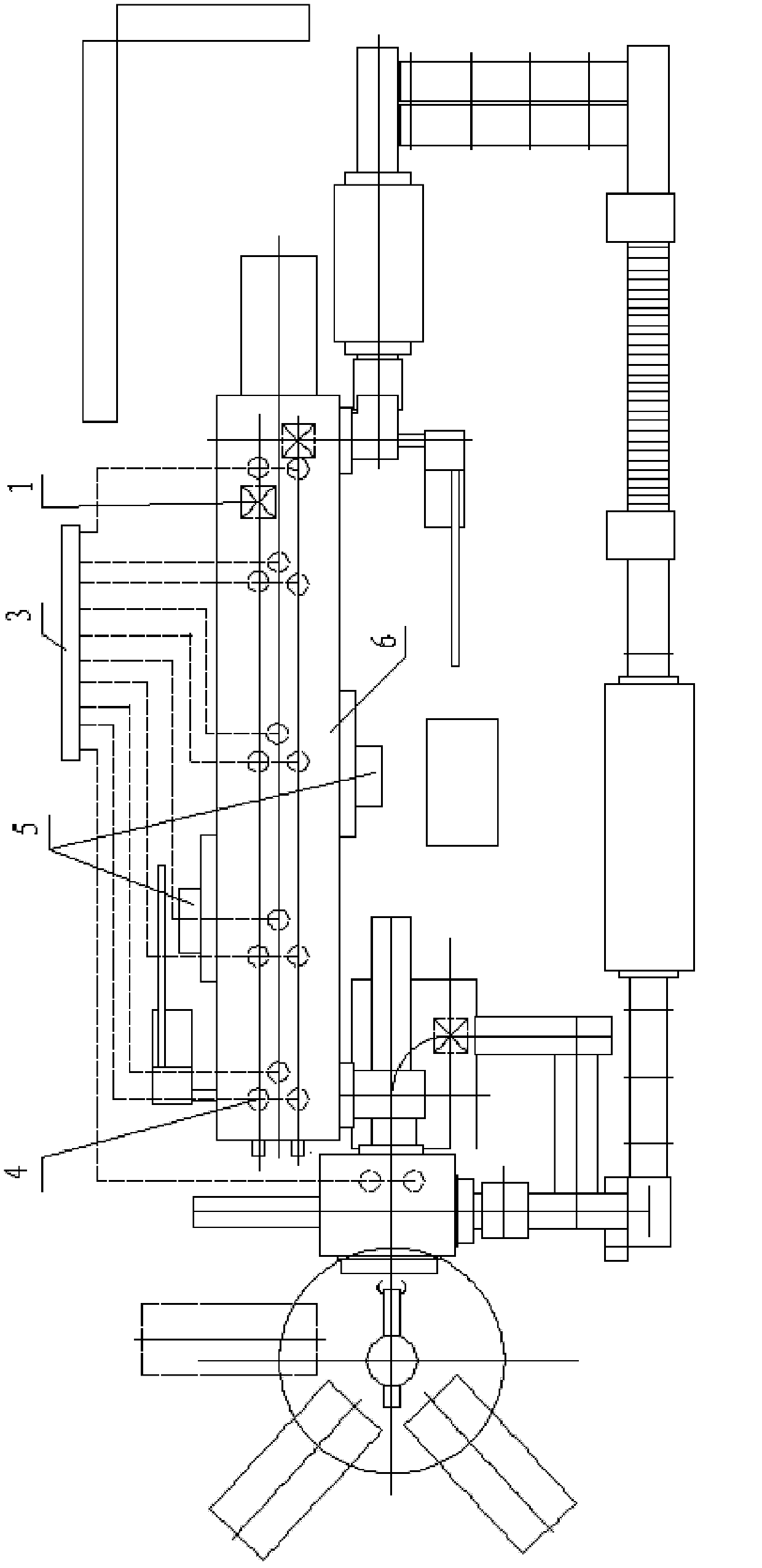
[0013] Specific implementation mode one: combine Figure 1 to Figure 17 The present embodiment will be described. This embodiment consists of a material pan 1, a heating device 2, a carburizing medium flow plate 3, a carburizing furnace water cooling anti-coking drip and nitrogen deplugging device 4, a direct-connected side fan 5 and a furnace body 6. The material pan 1 And the heating device 2 is set in the furnace body 6, the carburizing medium flow plate 3 is set outside the furnace body 6, the carburizing medium flow plate 3 is connected with the furnace body 6, and the carburizing furnace water cooling anti-coking instillation and nitrogen deplugging device 4 is connected with the furnace body 6, and the direct-connected side fan 5 is arranged on the side wall of the furnace body 6.

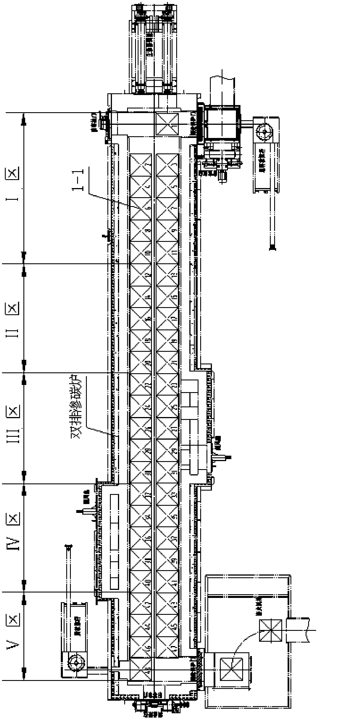
[0014] The described material tray 1 is calculated by the material tray 1-1 with 48 trays set in double rows, 10 trays are set in the heating zone, 10 trays are set in the soaking zone, 10 ...

specific Embodiment approach 2

[0020] Specific implementation mode two: combination figure 1 , image 3 The present embodiment will be described. The heating power of the heating zone (I zone) described in this embodiment is 200KW, and the heating power of the soaking zone (II zone) is also 200KW, which increases the heating power of the II section from the original 100KW to 200KW. The position of the temperature control point and the carbon potential control point is improved, which increases the heating speed of the workpiece, speeds up the recovery of the carburizing atmosphere and carbon potential in the furnace, and the recovery time of the carburizing atmosphere and carbon potential in each pushing cycle The original 15-20 minutes is shortened to 6-10 minutes, so that the position of the last two trays in the II section can evolve into a carburizing area, which relatively increases the carburizing area; the heating power of the carburizing area (III area) 100KW, 6 radiant heating tubes are arranged,...

specific Embodiment approach 3

[0021] Specific implementation mode three: combination Figure 4 , Figure 5 , Figure 9 The present embodiment will be described. The welded tee pipe joint 3-45 described in this embodiment consists of a steel pipe 3-45-1, a connecting pipe 3-45-2, a nut 3-45-3, an O-ring seal 3-45-4, and a type A The three-way joint body 3-45-5 is composed of one end of the connecting pipe 3-45-2 welded with the steel pipe 3-45-1, and the other end of the connecting pipe 3-45-2 is connected with the A-type tee joint body 3-45-5 An O-ring 3-45-4 is arranged between adjacent ends of the pipe, and the other end of the connecting pipe 3-45-2 is connected with the A-type tee joint body 3-45-5 by a nut 3-45-3.


PUM

PropertyMeasurementUnit
thicknessaaaaaaaaaa

Abstract

The invention relates to lorry spiral bevel gear double-row rare earth continuous gas carburization heat treatment equipment, which relates to automobile spiral bevel gear heat treatment carburization equipment and solves the problems that the defects of thick and big martensite needle and low level of the residue austenite are caused by poor uniformity of a carburization layer and high temperature (higher than the quenching temperature) of a V-region part, the carbon black is easy to generate, the carburization cost is high, the surface hardness of a carburization gear is low, the adhesion and abrasion resistance performance of a gear is poor, the service life is short, and a dripping pipe is easy to block. A material disc and a heating device are arranged in a furnace body, a carburization medium flow rate disc is arranged outside the furnace body and is connected with the furnace body, an anti-coking dripping and nitrogen blockage removing device of the carburization furnace is connected with the furnace body, and a direct connection type lateral fan is arranged on the side wall of the furnace body. The lorry spiral bevel gear double-row rare earth continuous gas carburization heat treatment equipment has the advantages that the operation cost is reduced, the heat treatment production efficiency and the product quality are improved, and the rare earth carburization technology is adopted, so the quality and the yield of the products are greatly improved.

Description

technical field [0001] The invention relates to carburizing heat treatment equipment for spiral bevel gears of automobiles, in particular to double-row rare earth continuous gas carburizing heat treatment equipment for spiral bevel gears of trucks. Background technique [0002] At present, the uniformity of the carburized layer of the carburized gear parts produced by the double-row continuous gas carburizing automatic production line is poor, and the temperature of the parts in the V zone is higher than the quenching temperature, resulting in the disadvantages of coarse martensitic needles and excessive grades of retained austenite ;It is easy to produce carbon black, the amount of methanol is large, the cost of carburizing is high, the hardness of the carburized gear surface is low, the performance of the gear against adhesive wear is poor, and the service life of the produced spiral bevel gear is short; double-row carburizing furnace equipment The failure rate is high; th...

Claims


Application Information

Patent Timeline
Patent Type & Authority Patents(China)
IPC IPC(8): C23C8/22
Inventor 金荣植谢飞刘志儒陈云生刘成友李庆文
Owner 哈尔滨汇隆汽车箱桥有限公司
Learn More