
Optical fiber plasma discharge laser amplification device and technology

A technology of micro-plasma and laser amplification, which is applied in the direction of lasers, phonon exciters, laser components, etc.

Inactive Publication Date: 2012-03-14
DALIAN NATIONALITIES UNIVERSITY
View PDF4 Cites 4 Cited by
  • Summary
  • Abstract
  • Description
  • Claims
  • Application Information

AI Technical Summary

Problems solved by technology

So far, there has been no report on the use of optical fiber microdischarge laser amplification technology

Method used


Image

  • Optical fiber plasma discharge laser amplification device and technology
  • Optical fiber plasma discharge laser amplification device and technology
  • Optical fiber plasma discharge laser amplification device and technology

Examples


Embodiment Construction

[0022] Below in conjunction with accompanying drawing and embodiment the utility model is further described.

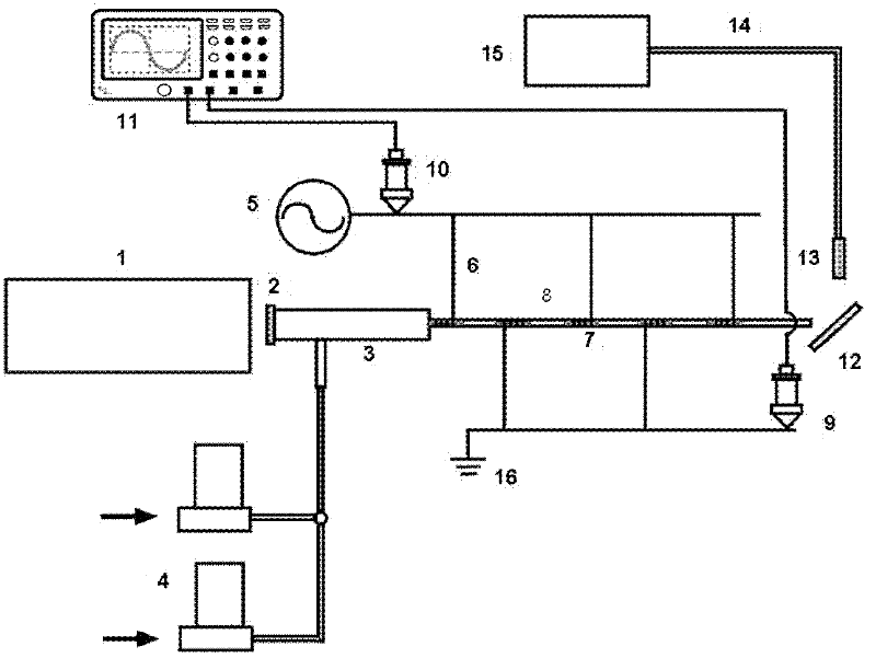
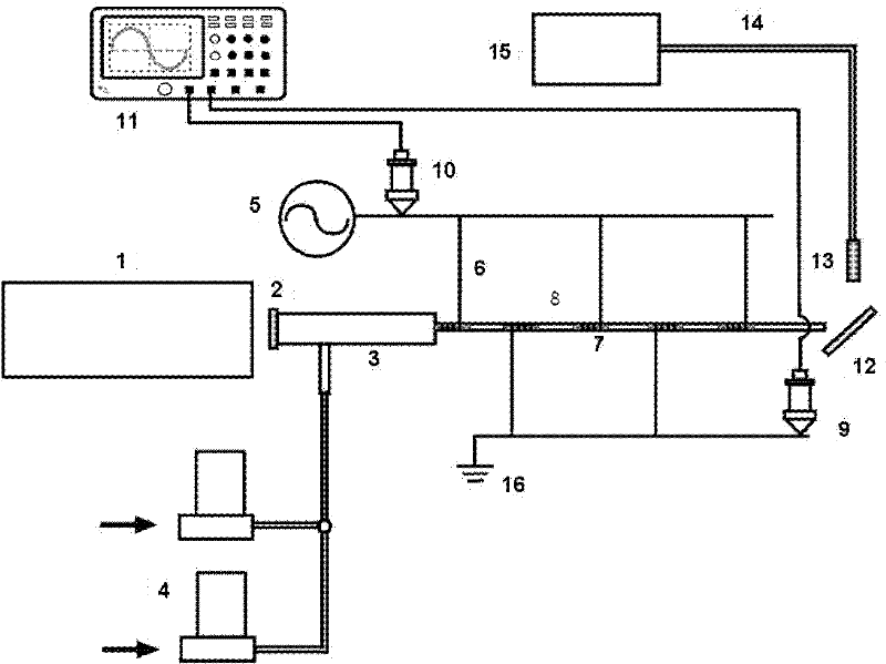
[0023] A kind of optical fiber micro-plasma discharge laser amplifying device, such as figure 1 As shown, the length of the optical fiber 8 for discharge is 150mm, and the outer wall of the optical fiber is wrapped with a copper ring 7 with a width of 10mm every 10mm, and the high voltage power supply 5 is alternately connected with a thin copper wire 6 (sinusoidal AC power supply, voltage adjustable range 0-20kV, Frequency adjustable range 0-20kHz) and ground wire 16. The ratio of the reaction gas is adjusted by the mass flow controller 4 and fully mixed in the quartz tube 3 at the rear end of the optical fiber. When the applied voltage peak-to-peak value is 4kV-9kV and the frequency is lower than 15kHz, a uniform and stable micro-plasma is generated. The helium-neon laser 1 emits a laser beam through the smooth quartz plate 2 at the end of the quartz tube and pass...


PUM


Abstract

The invention relates to an optical fiber plasma discharge laser amplification device and technology; the device comprises a quartz tube and an optical fiber for electro-discharge, wherein the quartz tube is used for mixing a helium gas and a neon gas; the optical fiber for electro-discharge is communicated at the front end of the quartz tube; and the outer wall of the optical fiber for electro-discharge is used for covering a metal electrode which is sequentially and alternatively connected with a high-voltage power supply and an earth wire. The technology comprises the following steps of: proportions of the helium reactive gas and the neon reactive gas are adjusted by a mass flow controller, the helium reactive gas and the neon reactive gas are fully mixed in a quartz tube, and uniform plasmas are generated at atmospheric pressure by using an inter-electrode alternative discharge structure; and laser beams which are emitted by a helium-neon laser pass through the optical fiber for electro-discharge through a smooth quartz plate at the tail end of the quartz tube to realize population inversion and slave machine irradiation, thereby realizing the amplification of lasers along thelaser transmission direction. The optical fiber plasma discharge laser amplification device has the characteristics that an electro-discharge manner is simple, complicated vacuum equipment is not needed, the equipment cost is low, the volume is small and the energy consumption is low.

Description

technical field [0001] The invention relates to the technique of using a micro-hole optical fiber to inject reaction gas (helium, neon) to generate a micro-plasma discharge under the condition of atmospheric pressure, so as to amplify the laser on the original basis. Background technique [0002] Laser is the radiation produced by the amplification of stimulated emission of light. It came into being under the background of theoretical preparation and urgent needs of production practice. Once it came out, it achieved unusually rapid development. The application fields of laser mainly include six fields: industry, medical treatment, commerce, scientific research, information and military affairs. Since the laser came out, due to its wide range of uses, it has caused a global research boom. Solid-state lasers, gas lasers, liquid lasers, semiconductor lasers, etc. came into being. Gas laser is a laser with gas or metal vapor as the main working substance. It is currently the l...

Claims


Application Information

Patent Timeline
IPC IPC(8): H01S3/0955H01S3/223
Inventor 刘东平宋颖
Owner DALIAN NATIONALITIES UNIVERSITY
Learn More