Low temperature rectification cascade system for rectifying CO to produce stable isotope 13C

A technology of stable isotope and low-temperature rectification, which is applied in the field of stable isotope separation of carbon, can solve the problems of large pressure drop in cascading devices, difficult construction, and high energy consumption of transportation equipment, and achieve the effect of continuous operation

Active Publication Date: 2012-03-21
SHANGHAI RES INST OF CHEM IND
View PDF2 Cites 19 Cited by
  • Summary
  • Abstract
  • Description
  • Claims
  • Application Information

AI Technical Summary

Problems solved by technology

However, due to the large number of theoretical plates required in the isotope separation process, the tower equipment is very high, so the construction is relatively difficult; in addition, due to the relatively large pressure drop of the cascade device, the separation coefficient between the isotope components is reduced, which is not good for separation.
In comparison, the construction difficulty of the horizontal cascade is much less, but, in the n-level horizontal cascade device of the prior art, the top feed and out...

Method used


Image

  • Low temperature rectification cascade system for rectifying CO to produce stable isotope 13C
  • Low temperature rectification cascade system for rectifying CO to produce stable isotope 13C
  • Low temperature rectification cascade system for rectifying CO to produce stable isotope 13C

Examples


Embodiment 1

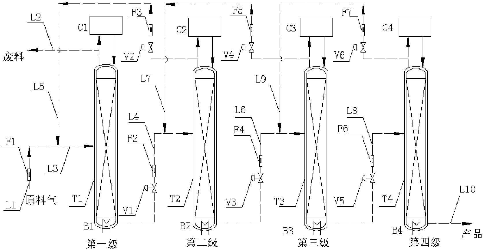
[0038] The cascade device in Example 1 consists of four-stage distillation towers. The process flow diagram of the cascade device is as follows figure 2 Shown. The CO raw material is measured by the flow meter F1 and transported from the line L3 to the middle of the first-stage tower T1. The T1 tower is filled with wire mesh corrugated packing, which is the reflux liquid condensed in the top condenser C1 and the bottom reboiler B1 The vaporized steam provides a surface for heat and mass transfer. Take out high-abundance carbon-12 from the top of T1 tower via line L2, take out a part of steam from the T1 tower kettle, measure it through valve V1 and flow meter F2 under the drive of pressure, and send it to the middle of tower T2 along line L4, T2 tower It is filled with metal wire mesh corrugated packing to provide heat and mass transfer surfaces for the refluxed liquid in the condenser C2 at the top of the tower and the vaporized vapor in the reboiler B2 at the bottom of the t...

Embodiment 2

[0044] The cascade device in Example 2 is composed of four-stage distillation towers. The process flow diagram of the cascade device is as follows Figure 4 Shown. The CO raw material is measured by the flow meter F1 and transported from the line L3 to the middle of the first-stage tower T1. The T1 tower is filled with wire mesh corrugated packing, which is the reflux liquid condensed in the top condenser C1 and the bottom reboiler B1 The vaporized steam provides a surface for heat and mass transfer. Take out high-abundance carbon-12 from the top of T1 tower via line L2, take out a part of steam from the T1 tower kettle, drive by pressure via valve V1 and flow meter F2, and then send it to the middle of tower T2 along line L4 ( Figure 4 Midpoint d), the T2 tower is filled with wire mesh corrugated packing to provide heat and mass transfer surfaces for the refluxed liquid in the condenser C2 at the top of the tower and the vaporized vapor in the reboiler B2 at the bottom of the ...

Embodiment 3

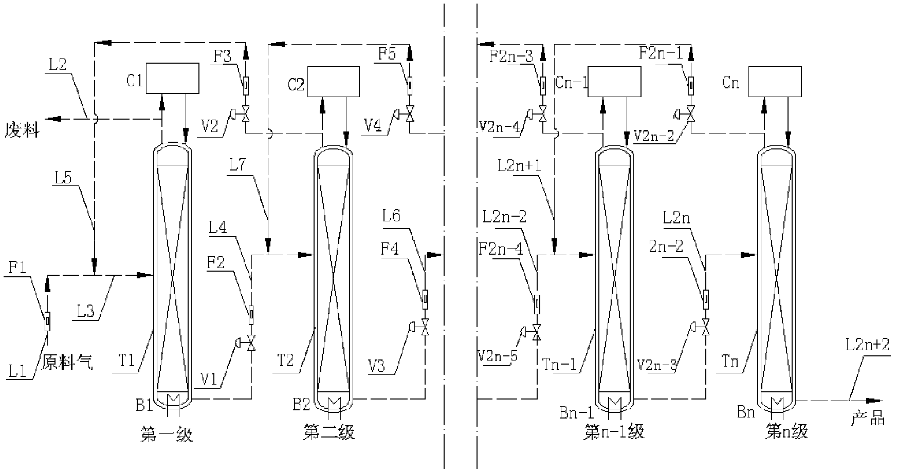
[0050] A kind of rectified CO to produce stable isotope 13 C's cryogenic rectification cascade system is a cascade device composed of two horizontally placed rectification towers with gradually narrower diameters. The rectification tower consists of a top condenser, a bottom reboiler and a rectification column. The rectification towers are connected by pipelines. The first-stage rectification tower inputs the raw materials from the middle part, and the vapor from the top of the later-stage rectification tower is transported to the middle part of the front-stage rectification tower by pressure through the pipeline. The liquid produced in the bottom of the front-stage rectification tower is vaporized in the pipeline It is transported to the middle of the post-rectification tower under pressure, and the vapor from the top of the post-rectification tower can enter the front-stage rectification tower at the feed point of the previous-stage rectification tower. The rectification towe...


PUM


Abstract

The invention relates to a low temperature rectification cascade system for rectifying CO to produce stable isotope 13C. The low temperature rectification cascade system is a cascade unit comprising n stage rectifying towers that are arranged horizontally; the rectifying towers comprise overhead condensers, tower bottom reboilers and rectifying columns; and the rectifying towers are connected through pipelines. Compared with the prior art, extraction sections are arranged in the horizontally cascaded rectifying towers so as to reduce the material conveying flow rate between cascaded rectifying towers, the automatic material flow between the rectifying towers can be achieved at the same time by changing the pressure distribution of the horizontal cascade system, the material is conveyed among the intermediate rectifying towers without power conveying equipment, and the cascade unit can be ensured to operate stably and continuously for a long time.

Description

Technical field [0001] The invention relates to a carbon stable isotope separation technology, in particular to a rectified CO production stable isotope 13 C's cryogenic distillation cascade system. Background technique [0002] In carbon-containing compounds, carbon is a stable isotope 12 C, 13 C and radioactivity 14 C exists in nature, where 12 C and 13 The natural abundance ratio of C is about 98.9:1.1. With the development of technology, 13 As a tracer atom, C has been widely used in the fields of medicine, pharmacology, biochemistry and life sciences. In addition, the high abundance 12 The better physical properties of C synthetic diamonds than natural products have also attracted attention. [0003] In the prior art, there are already many stable isotopes 13 C production methods, such as thermal diffusion method, gas diffusion method, chemical exchange method, cryogenic distillation method, laser method, etc. Among them, the cryogenic distillation method is produced in indu...

Claims


Application Information

Patent Timeline
IPC IPC(8): B01D59/04
Inventor 许保云李虎林陈大昌李良君杜晓宁周建跃蔡扬龙磊吉永喆
Owner SHANGHAI RES INST OF CHEM IND
Why Eureka
Try Eureka