Large-temperature-difference concentrated energy station refrigerating system

A technology of refrigeration system and energy station, applied in air-conditioning system, water shower cooler, household heating and other directions, can solve the problems of large conveying flow and waste of conveying power consumption, etc., to improve conveying efficiency, reduce conveying energy consumption, improve Effect of return water temperature

Pending Publication Date: 2021-05-14
珠海横琴能源发展有限公司
View PDF6 Cites 1 Cited by
  • Summary
  • Abstract
  • Description
  • Claims
  • Application Information

AI Technical Summary

Problems solved by technology

[0007] The purpose of the present invention is to provide a large temperature difference centralized energy station refrigeration system to solve the problems in the prior art that the cooling mode with small temperature difference will cause a lot of waste of transmission power consumption and large transmission flow

Method used


Image

  • Large-temperature-difference concentrated energy station refrigerating system
  • Large-temperature-difference concentrated energy station refrigerating system

Examples


Embodiment 1

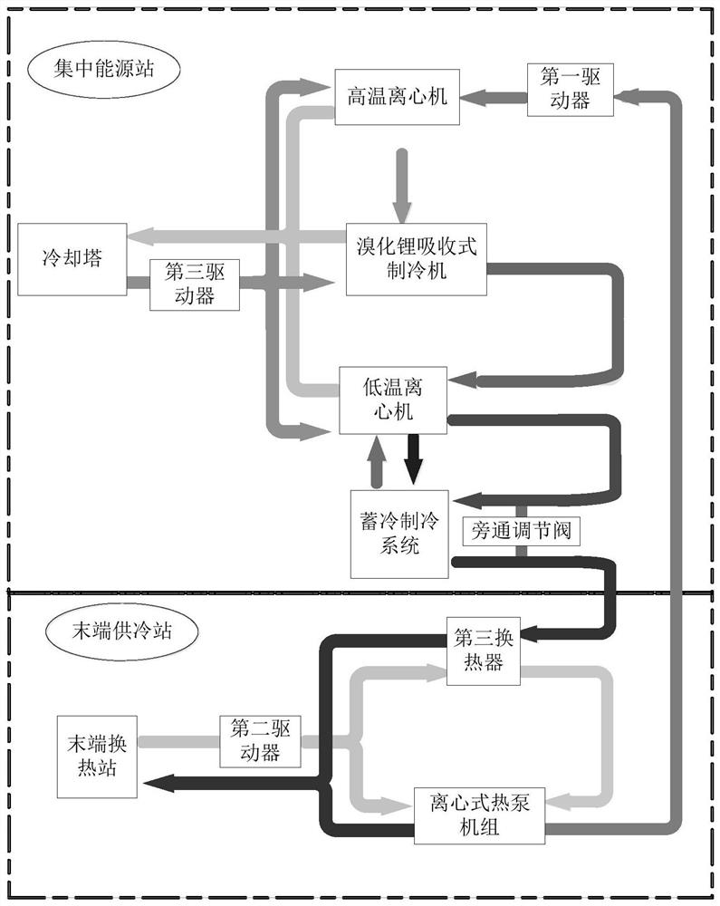
[0028] figure 1 It is a connection block diagram of a structure of the large temperature difference centralized energy station refrigeration system in the present invention, such as figure 1 As shown, this embodiment discloses a large temperature difference centralized energy station refrigeration system, including:

[0029] A centralized energy station, which is used to provide cooling water for the terminal cooling station;

[0030] The terminal cooling station is used to exchange heat with the terminal heat exchange station through cooling water, and is also used to provide the return water after heat exchange to the centralized energy station; the terminal cooling station is also equipped with a centrifugal heat pump unit, the The centrifugal heat pump unit is used to increase the temperature of the return water, so that the temperature difference between it and the cooling water is not less than 20°C;

[0031] A circulating delivery pipeline, which is arranged between t...

Embodiment 2

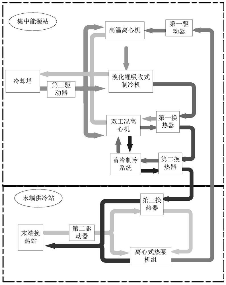
[0042] figure 2 It is a connection block diagram of another structure of the refrigeration system of the central energy station with large temperature difference in the present invention, such as figure 2 As shown, most of the structure of this embodiment is the same as that of Embodiment 1, the difference is that the low-temperature centrifuge in the refrigeration mechanism is replaced by a double-working condition centrifugal unit, and a second communication circuit is provided between the cold storage refrigeration system, and the Used to make ice for cold storage refrigeration system. Specifically, the refrigeration mechanism includes a high-temperature centrifuge, a lithium bromide absorption refrigerator, a dual-working condition centrifugal unit, and a cold storage refrigeration system. The systems are all equipped with cooling passages, and the cooling passages are connected in sequence; the cold storage refrigeration system is provided with an ice storage tank, and a...


PUM


Abstract

The invention belongs to the technical field of cooling systems, and particularly relates to a large-temperature-difference concentrated energy station refrigerating system. The large-temperature-difference concentrated energy station refrigerating system comprises a concentrated energy station, a tail end cooling station and a circulating conveying pipeline, wherein the concentrated energy station is used for providing cooling water for the tail end cooling station; the tail end cooling station is used for carrying out heat exchange with a tail end heat exchange station through the cooling water and is further used for providing return water after heat exchange for the concentrated energy station; the tail end cooling station is further provided with a centrifugal heat pump unit, and the centrifugal heat pump unit is used for increasing the temperature of the return water, so that the temperature difference between the return water and the cooling water is not less than 20 DEG C; and the circulating conveying pipeline is arranged between the concentrated energy station and the tail end cooling station and is used for conveying the cooling water and the return water. Through the arrangement, the conveying temperature difference of the chilled water is improved, and then the conveying efficiency of the chilled water is improved or the cooling load capacity increase is realized for a built project.

Description

technical field [0001] The invention belongs to the technical field of refrigeration systems, and in particular relates to a refrigeration system of a centralized energy station with a large temperature difference. Background technique [0002] The central air-conditioning system is a "big energy consumer" in buildings. The cooling system of several energy stations can help improve cooling energy efficiency, reduce cooling energy consumption, reduce environmental pollution, and reduce the urban heat island effect. With the construction of new urban districts, the construction of several large-scale energy stations is increasing. [0003] The main disadvantage of district cooling is the three problems brought about by the increase of cold water transportation distance: high energy consumption in transportation; large investment in pipe network; large cooling loss in pipe network. Transmission energy consumption and pipeline network investment are related to the amount of wat...

Claims


Application Information

Patent Timeline
Patent Type & Authority Applications(China)
IPC IPC(8): F24F5/00F24F13/30F28C1/00
CPCF24F5/0007F24F5/0014F24F5/0017F24F13/30F28C1/00Y02E60/14
Inventor 徐朝阳刘磊曾贺湛毛世权韩宇波欧志才
Owner 珠海横琴能源发展有限公司
Why Eureka
Try Eureka