Process for production of fluorescent substance
A technology of fluorescent substances and phosphors, applied in chemical instruments and methods, luminescent materials, nitrogen compounds, etc., can solve problems such as intractable, expensive compounds, chemical instability, etc.
- Summary
- Abstract
- Description
- Claims
- Application Information
AI Technical Summary
Problems solved by technology
Method used
Image
Examples
Embodiment 1
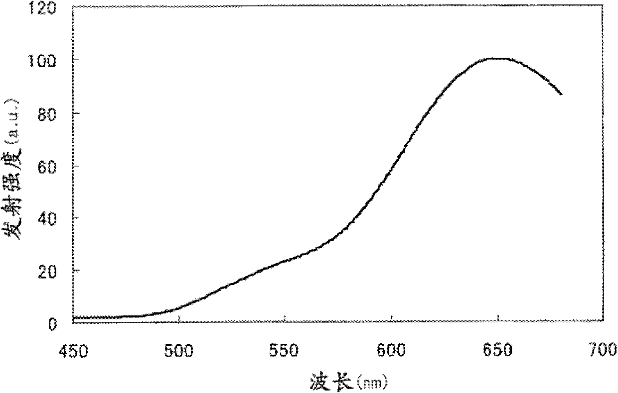
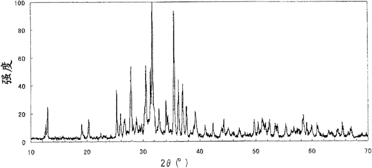
[0067] Weigh 7.46g SrO, 1.41g Eu respectively 2 o 3 and 5.62g Si powder as raw material and dry mixed. In the obtained mixture, the composition ratio (molar ratio) of elements Sr:Eu:Si was 1.8:0.2:5.0. Put the mixture in a BN container, and then place H in it at 1500°C under atmospheric pressure 2 and N 2 The flow rates were respectively 5 L / min and 5 L / min in a reducing atmosphere for 8 hours to obtain the intermediate product in the first step. This intermediate emits orange light with a peak at about 650 nm when excited by 365 nm UV light. The observed emission spectra are shown in figure 1 middle. In addition, the intermediate product was measured by X-ray diffraction using Cu-Kα line to obtain figure 2 The diffraction pattern shown. The diffraction pattern has many diffraction lines corresponding to the lines of the pattern shown by Xie et al. in Chem. 2 Si 5 N 8 components shown. This intermediate product was then subjected to compositional analysis to dete...
Embodiment 2
[0070] Weigh 9.33g SrO, 1.76g Eu respectively 2 o 3 and 4.68g Si 3 N 4 As raw material and dry blended. In the obtained mixture, the composition ratio (molar ratio) of elements Sr:Eu:Si was 0.9:0.1:1.0. Put the mixture in a container made of SiC, and then place H in it under atmospheric pressure at 1400°C 2 and N 2 The flow rates were respectively 5 L / min and 5 L / min in a reducing atmosphere for 8 hours to obtain the intermediate product in the first step. This intermediate emits orange light with a peak at about 640 nm when excited by 365 nm UV light. In addition, the intermediate product was subjected to X-ray diffraction measurement, thereby confirming that it contained (Sr, Eu) 2 Si 5 N 8 components shown. This intermediate product was then subjected to compositional analysis to determine the molar ratio of oxygen to the sum of strontium and europium. As a result, the ratio was found to be 0.73, thus proving that the intermediate product contained only a small a...
Embodiment 3 and 4
[0073] Weigh 10.95g Sr(OH) respectively 2 , 1.76g Eu 2 o 3 and 5.62g Si powder as raw material and dry mixed. In the obtained mixture, the composition ratio (molar ratio) of elements Sr:Eu:Si was 0.9:0.1:2.0. Put the mixture in a BN container, and then at 1600°C under atmospheric pressure, Hx and N 2The flow rates were respectively 5 L / min and 5 L / min in a reducing atmosphere for 8 hours to obtain the intermediate product in the first step. This intermediate emits yellow-orange light with a peak at about 650 nm when excited by 365 nm UV light. In addition, the intermediate product was subjected to X-ray diffraction measurement, and thus proved to contain (Sr, Eu) 2 Si 5 N 8 components shown. This intermediate product was then subjected to compositional analysis to determine the molar ratio of oxygen to the sum of strontium and europium. As a result, the ratio was found to be 0.34, thus proving that the intermediate product contained only a small amount of oxygen.
[...
PUM
| Property | Measurement | Unit |
|---|---|---|
| particle size | aaaaa | aaaaa |
Abstract
Description
Claims
Application Information
 - R&D
- Intellectual Property
- Life Sciences
- Materials
- Tech Scout
- Unparalleled Data Quality
- Higher Quality Content
- 60% Fewer Hallucinations
Browse by: Latest US Patents, China's latest patents, Technical Efficacy Thesaurus, Application Domain, Technology Topic, Popular Technical Reports.
© 2025 PatSnap. All rights reserved.Legal|Privacy policy|Modern Slavery Act Transparency Statement|Sitemap|About US| Contact US: help@patsnap.com


