
Logic control loop for rock drilling operations of hydraulic rock drilling machine

A technology of rock drilling rig and action logic, which is applied in the field of compound logic control circuit of hydraulic rock drilling rig, can solve problems such as poor adaptability, broken drill rod, inability to realize automatic matching of key rock drilling actions, compound logic control, etc. To achieve the effect of improving drilling efficiency

Active Publication Date: 2012-03-21
SUNWARD INTELLIGENT EQUIP CO LTD
View PDF8 Cites 8 Cited by
  • Summary
  • Abstract
  • Description
  • Claims
  • Application Information

AI Technical Summary

Problems solved by technology

However, the remaining problems are poor reliability and poor adaptability of rock drilling, drill tail breakage, drill rod breakage, drill sticking, failure to pass through interlayer geology and other application bottlenecks, which seriously restrict the application and promotion of this new product
The full-power throttling hydraulic system of small excavators is used to control hydraulic rock drills. It can only realize the independent and non-adjustable control of the three key rock drilling actions of impact, rotation, and advancement, and cannot realize the automatic matching and compounding of the three key rock drilling actions. logic control

Method used


Image

  • Logic control loop for rock drilling operations of hydraulic rock drilling machine
  • Logic control loop for rock drilling operations of hydraulic rock drilling machine
  • Logic control loop for rock drilling operations of hydraulic rock drilling machine

Examples


Embodiment Construction

[0013] Below in conjunction with accompanying drawing, specific embodiment of the present invention is described in further detail:

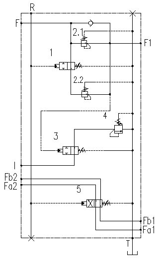
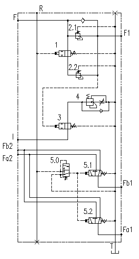
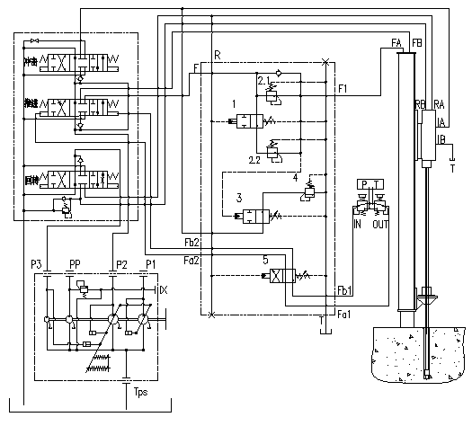
[0014] Such as figure 1 and image 3 In the first embodiment shown, hydraulically controlled directional valve 1, pressure reducing valve 2.1, pressure reducing valve 2.2, hydraulically controlled directional valve 3, and overflow valve 4 form a rotary pressure to control two-stage pressure propulsion, while low pressure propulsion controls low pressure impact Logical control loop; hydraulically controlled reversing valve 3 and overflow valve 4 form a logic control loop for propulsion pressure control, high and low, two-stage impact pressure; two-position, four-way hydraulically controlled reversing valve 5 constitutes a logical control loop for rotary pressure control, propulsion and lifting .

[0015] The rotary pressure is introduced into the rock drilling action logic control block from the rotary main oil circuit through the oil port R, a...


PUM


Abstract

The invention discloses a logic control loop for rock drilling operations of a hydraulic rock drilling machine. A first hydraulic control reversing valve, a first pressure reducing valve, a second pressure reducing valve, a second hydraulic control reversing valve and an overflow valve or a speed adjusting valve form the logic control loop for controlling two-stage pressure propulsion by rotary pressure and controlling low-pressure impact by low-pressure propulsion at the same time; the second hydraulic control reversing valve and the overflow valve or the speed adjusting valve form the logic control loop for controlling two-stage impact pressure by propelling pressure; and the hydraulic control reversing valves form the logic control loop for controlling propulsion and lift by rotary pressure. Through the logic control loop, automatic matching and composite logic control of three key rock drilling operations, namely impact, rotation and propulsion of the rock drilling machine are realized, and the adaptability and the reliability of the rock drilling operations are improved.

Description

technical field [0001] The invention relates to a composite logic control circuit for rock drilling actions of a hydraulic rock drilling rig, in particular to a composite logic control circuit for a hydraulic rock drilling rig to realize the three key rock drilling actions of impact, rotation and propulsion. Background technique [0002] Hydraulic rock drilling rigs are widely used in rock drilling operations due to their advantages of high efficiency and energy saving. The working conditions of rock drilling and drilling are harsh and complicated, and the specific performance is that according to different rock types and hardness, the three key rock drilling actions of impact, rotation, and advancement need to have good adjustability; adapt to caves, cracks, and interlayers in rock formations And other complex geology, the three key rock drilling actions of impact, rotation and propulsion and their matching are equipped with automatic logic control, automatic anti-air strik...

Claims


Application Information

Patent Timeline
Patent Type & Authority Applications(China)
IPC IPC(8): E21B44/00F15B11/02
Inventor 王东升刘鹏赵宏强曾素林宏武
Owner SUNWARD INTELLIGENT EQUIP CO LTD
Learn More