Horizontal shaft pitch-control tide energy water turbine

A technology of variable pitch and tidal current energy, which is applied in the direction of electromechanical devices, mechanical equipment, hydroelectric power generation, etc., can solve the problems of inability to realize efficient conversion and utilization of tidal current energy, inability to realize low flow rate self-starting, current instability, etc., and achieve simplified structure and control complexity, reduce system complexity, and reduce the effect of blade load

Inactive Publication Date: 2012-03-21
HARBIN ENG UNIV
View PDF5 Cites 8 Cited by
  • Summary
  • Abstract
  • Description
  • Claims
  • Application Information

AI Technical Summary

Problems solved by technology

[0003] At present, the common horizontal-axis tidal energy turbines are mostly fixed-pitch turbines. Due to the periodicity and bidirectionality of the tidal current, the tidal flow velocity changes periodically within a certain range. The efficient conversion and utilization of tidal current energy cannot be realized, resulting in the instability of the generated current, the impact of grid connection, the increase of cost and the waste of tidal current energy
In addition, the common tidal energy turbines with horizontal axis and fixed pitch need to install additional devices such as brakes to ensure the normal operation of the turbines. The cost is high, and the loss is quite large under severe working conditions or sudden dangers, especially the damage of the blades.

Method used


Image

  • Horizontal shaft pitch-control tide energy water turbine
  • Horizontal shaft pitch-control tide energy water turbine
  • Horizontal shaft pitch-control tide energy water turbine

Examples


Embodiment Construction

[0025] The present invention is described in more detail below in conjunction with accompanying drawing example:

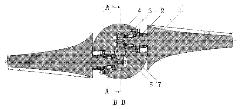
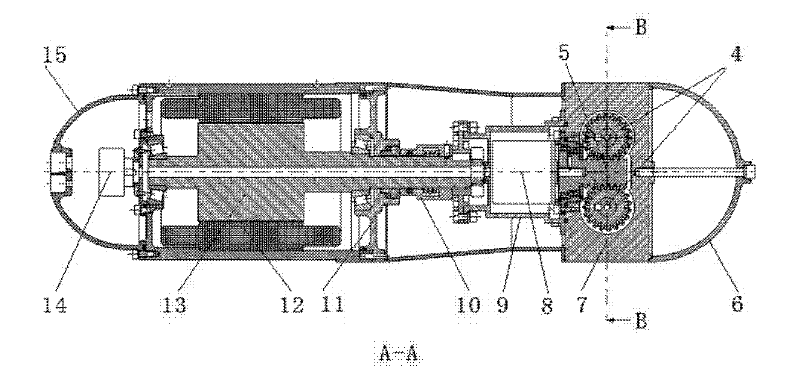
[0026] combine Figure 1-6 , the present invention is a horizontal axis variable pitch tidal current energy turbine, the pitch system of which is connected to the rotor 13 of the generator system through the flange 9, and the generator system is installed on the shuttle-shaped vertical rod 17 of the swing head assembly through the box body 11; Under the impact of the water flow, the swing head assembly makes the water turbine 17 automatically align with the direction of the water flow, and the variable pitch system adjusts the speed and torque of the impeller, drives the generator system to work through the flange 9, and outputs electric energy.

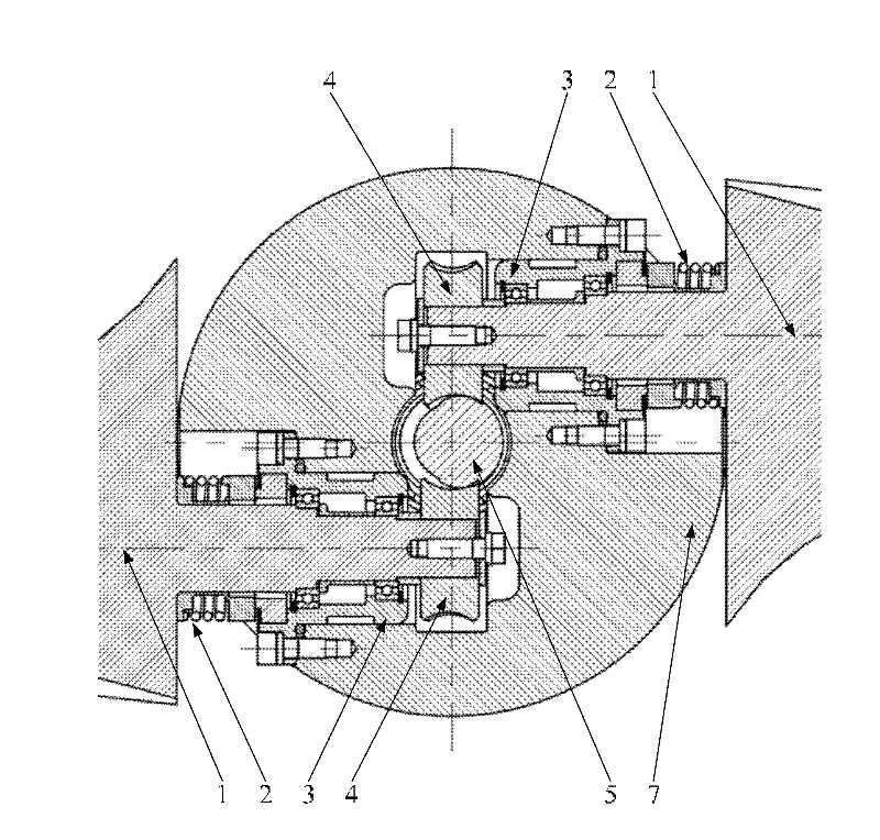
[0027] Such as figure 1 , figure 2 , image 3 , Figure 4 As shown, the dynamic seal A2 and the blade cup 3 are sequentially installed between the blade 1 and the turntable 7, the worm wheel 4 is fixedly connected t...


PUM


Abstract

The invention aims to provide a horizontal shaft pitch-control tide energy water turbine. The water turbine comprises a front hatch cover, a rear hatch cover, a generator system, a pitch control system and a yaw assembly, wherein the generator system comprises a generator rotor, a coil and a box, the coil is fixed on the box, and the generator rotor is positioned in the coil; the pitch control system comprises a paddle, a worm wheel, a worm, a paddle-changing motor, and a turnplate; the paddle-changing motor is used for driving the worm, the worm is arranged on the turnplate and meshed with the worm wheel, and the worm wheel is fixedly connected with the paddle; the snaking assembly comprises a shuttle upright, a revolute joint and a rack, the shuttle upright is connected with the revolute joint, the revolute joint is connected with the rack, and the shuttle upright rotates on the rack through the revolute joint; and the pitch control system is connected with the generator rotor through a flange, the front hatch cover is connected with the turnplate, the rear hatch cover is connected with the generator system, and the shuttle upright is connected with the box. The water turbine provided by the invention has the advantages of simple system and high reliability, low cost, convenience in maintenance, and has a slower flow rate self-starting performance.

Description

technical field [0001] The invention relates to a hydroelectric power generation equipment. Background technique [0002] As the overexploitation of fossil resources is on the verge of depletion and the resulting environmental problems are becoming more and more serious, clean and renewable energy has attracted worldwide attention. The ocean area accounts for 71% of the earth and contains huge energy. Ocean current power generation has a long history, and there are various forms of development and utilization, most of which are impeller machines, which can be divided into vertical axis type (the direction of impeller rotation is perpendicular to the water surface) and horizontal axis type (horizontal axis type can also be divided into impeller rotation spindle Parallel and perpendicular to the direction of water flow). The vertical shaft type uses the torque difference of the vertical blades on both sides of the impeller to rotate the impeller, and the power generation eff...

Claims


Application Information

Patent Timeline
Patent Type & Authority Applications(China)
IPC IPC(8): F03B13/26F03B3/00F03B3/14H02K7/18
CPCY02E10/28Y02E10/223Y02E10/20Y02E10/30
Inventor 孔凡凯谢哲张敏
Owner HARBIN ENG UNIV
Why Eureka
Try Eureka