Battery control system and vehicle system with battery control system
A battery control and battery technology, which is applied in the field of vehicle systems and battery control devices, can solve the problems of reduced energy saving effect and achieve the effect of prolonging battery life
- Summary
- Abstract
- Description
- Claims
- Application Information
AI Technical Summary
Problems solved by technology
Method used
Image

Examples
Embodiment 1
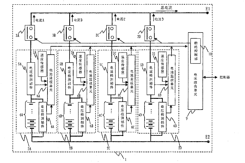
[0046] figure 1 A configuration example of the battery control device in the present invention is shown.
[0047] The battery control device 1 is composed of battery modules 2A to 2D, circuit breakers 3A to 3D that freely switch between the energized state and the disconnected state, and a battery integrated unit 9 that controls the entire control device.
[0048] In addition, the battery modules 2A to 2D include battery packs 4A to 4D composed of a plurality of battery cells, current detection parts 5A to 5D for detecting current flowing through the battery packs, and voltage detection parts 6A to 5D for detecting pack voltages of the battery packs. 6D, temperature sensors 7A to 7D that measure the temperature in the module, and battery monitoring units 8A to 8D that monitor each battery. Inverters and the like are connected to E1 and E2.
[0049]The battery packs 4A to 4D are units in which a plurality of batteries capable of storing and releasing electric energy such as n...
Embodiment 2
[0080] In this embodiment, a setting method of a timeout in consideration of the degree of deterioration of each of the battery packs 4A to 4D constituting the battery modules 2A to 2D of the battery control device 1 will be described. The unbalanced degree of deterioration is due to individual differences in batteries or differences in the magnitude of the flowing current. In addition, due to failure or the like, only a part of the batteries need to be replaced with new ones.
[0081] From this, it can be seen that, when charging and discharging the battery packs 4A to 4D for the modules having a difference in degree of deterioration among the batteries of the battery packs 4A to 4D, the battery packs 4A to 4D can be charged and discharged so that the degrees of deterioration are equalized, and as a result, a longer life can be achieved. .
[0082] As an index of the degree of deterioration, the same resistance increase rate defined by the internal resistance value as in Exa...
Embodiment 3
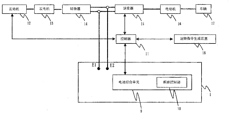
[0087] In this embodiment, a case where there are a plurality of battery control devices each including a plurality of modules, and a timeout is provided between the battery control devices will be described. As an example, a case where one battery control device is installed and operated in each of the leading vehicle and the trailing vehicle of the hybrid railway is given.
[0088] Figure 11 The system at this time is shown. The part shown at 20A is the drive system A of the leading vehicle, and the part shown at 20B is the drive system of the trailing vehicle. Each drive system includes an engine 12 , a generator 13 , a converter 14 , an inverter 15 , a controller 11 , and a battery control device 1 including a plurality of modules. Each drive system transmits electric power obtained from the engine or battery control unit to the electric motor to drive the axle. In addition, at the time of deceleration, the electric motor charges the battery pack of the battery control...
PUM
 Abstract
Description
Claims
Application Information
 - R&D
- Intellectual Property
- Life Sciences
- Materials
- Tech Scout
- Unparalleled Data Quality
- Higher Quality Content
- 60% Fewer Hallucinations
Browse by: Latest US Patents, China's latest patents, Technical Efficacy Thesaurus, Application Domain, Technology Topic, Popular Technical Reports.
© 2025 PatSnap. All rights reserved.Legal|Privacy policy|Modern Slavery Act Transparency Statement|Sitemap|About US| Contact US: help@patsnap.com