
System for testing particle moving speed based on single image

A technology of particle motion and single image, applied in fluid velocity measurement, velocity/acceleration/impact measurement, particle size analysis, etc., can solve the problems of high output light intensity of laser, unadjustable position, expensive PIV test equipment, etc., to achieve Improve the exposure intensity to meet the test requirements

Inactive Publication Date: 2012-03-28
NANJING UNIV OF SCI & TECH
View PDF6 Cites 29 Cited by
  • Summary
  • Abstract
  • Description
  • Claims
  • Application Information

AI Technical Summary

Problems solved by technology

But their disadvantages are: because the above schemes either use a double-pulse laser with a pulse width of nanoseconds or a high-speed camera, which makes the PIV test equipment expensive; in addition, the lenses are fixed at the vertical position of the test area Nearby, the position cannot be adjusted, and the weak scattered light in the vertical direction of the particles is mainly used in the test, so the output light intensity of the laser is very high; in addition, these two solutions cannot obtain real-time information on the particle speed and motion direction between two exposures. Changes

Method used


Image

  • System for testing particle moving speed based on single image
  • System for testing particle moving speed based on single image
  • System for testing particle moving speed based on single image

Examples


Embodiment Construction

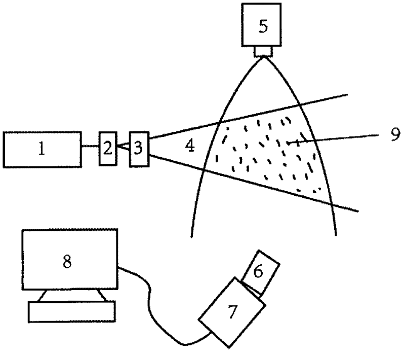
[0012] The specific structural principles of the present invention will be further described in detail below in conjunction with the accompanying drawings, taking the application of the present invention in spray testing as an example. The following examples can enable those skilled in the art to understand the present invention more fully, but do not limit the present invention in any way.

[0013] see figure 1 , the particle motion speed test system based on a single image for spray testing made according to the present invention, it is made of laser 1, cylindrical lens 2, adjustable slit 3, spray nozzle 5, shifting lens 6, camera 7 and computer 8 components, the laser 1 is a continuous laser, its output power is 200mW, the diameter of the cylindrical lens 2 is 8mm, the slit width of the adjustable slit 3 can be adjusted from 0 to 10mm, the cylindrical lens 2 and the adjustable slit 3 are set on the continuous laser 1 on the output optical path, the spray area of ​​the nozz...


PUM


Abstract

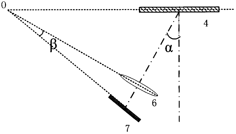
The invention discloses a system for testing the particle moving speed based on a single image. In the system, a continuous laser is taken as a laser light source, and a shift lens is taken as a camera lens; by adjusting the horizontal position of the shift lens, the shift lens is deviated from a sheet light source along the vertical direction by a certain angle, and the exposure intensity of a particle image is remarkably increased; and by adjusting an included angle between the shift lens and a camera sensitive surface, planes where the shift lens, the light sensitive surface of the camera and the sheet light source are intersected on a straight line, and clear imaging of all particles in a testing area is realized. In the invention, the exposure time is controlled by using the camera, changes of the speed and moving direction of the particles within the expose time can be reflected in real time only by acquiring a single image of the particle moving, and parameters such as speed change and distribution of particles in a flow field, particle diameter distribution of the particles and the like can be obtained by processing. The system has low equipment cost and low manufacturing cost, and can be applied to particle parameter testing of various atomization and flow fields.

Description

technical field [0001] The invention relates to a particle imaging test system, in particular to a test system for obtaining particle motion velocity from a single image obtained by controlling the exposure time of a camera. Background technique [0002] Particle Image Velocimetry (PIV for short) is a speed measurement technology based on optical images, which records the position of particles in the flow field on the image medium by tracing the light scattering effect of particles scattered in the fluid. Then use the followability of the particles to the flow field to measure the velocity of the fluid in which the particles are located. [0003] At present, in the particle imaging velocimetry technology, a special double-pulse laser with a pulse width of nanoseconds is usually used to illuminate the particles in a specific plane twice within a certain time interval, and the secondary illumination is obtained by using photography technology. The instantaneous particle image...

Claims


Application Information

Patent Timeline
Patent Type & Authority Applications(China)
IPC IPC(8): G01P5/20G01N15/02
Inventor 张宏超倪晓武王振东陆建沈中华
Owner NANJING UNIV OF SCI & TECH
Learn More