Microgrid coordination control system and method based on state transition

A coordinated control system and state transition technology, applied in the direction of AC network circuit, AC network load balancing, single network parallel feeding arrangement, etc., can solve the problem of not being able to quickly respond to load changes, affecting the quality of output power, and slow response speed of micro-sources, etc. problems, to achieve the effect of ensuring uninterrupted power supply, improving power supply quality, and improving operation reliability

Inactive Publication Date: 2012-03-28
CHONGQING UNIV
View PDF2 Cites 36 Cited by
  • Summary
  • Abstract
  • Description
  • Claims
  • Application Information

AI Technical Summary

Problems solved by technology

2. Provide high-quality electric energy: due to the slow response speed and small inertia of the micro-source, and it is easily affected by the change of the primary energy supply, when the load changes, the micro-source cannot respond to the load change quickly, which affects the quality of the output power

Method used


Image

  • Microgrid coordination control system and method based on state transition
  • Microgrid coordination control system and method based on state transition
  • Microgrid coordination control system and method based on state transition

Examples


Embodiment Construction

[0023] The present invention will be further described in detail below in conjunction with the accompanying drawings and specific embodiments.

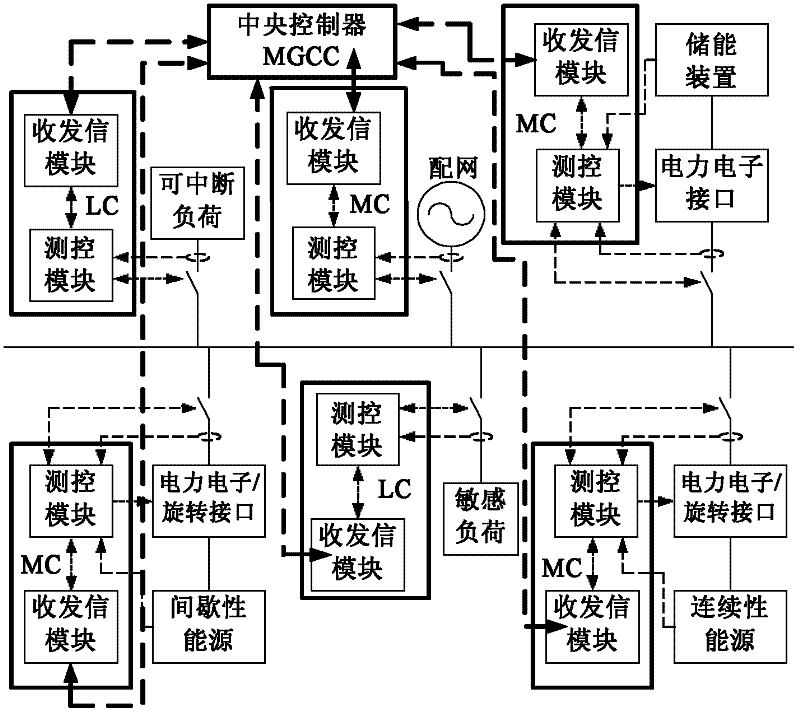
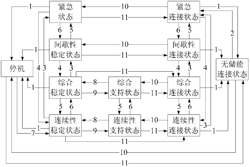
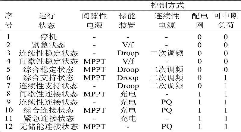
[0024] In the microgrid system, it involves six parts: interruptible load, sensitive load, distribution network, intermittent energy source, continuous energy source and energy storage device, and each part involves the corresponding control element: circuit breaker, power electronic interface or rotary interface, load switch. The idea of ​​the present invention is to first collect the information of these six major parts, including the output power of each micro-source, the voltage frequency amplitude of the system bus, the voltage frequency amplitude of the distribution network, the status of the load switch, the switch status of the tie line, etc. The central controller calculates the operating status of the decision-making system and the control of each component of the micro-grid according to the information of the micro-grid sys...


PUM


Abstract

The invention discloses microgrid coordination control system and method based on state transition. The microgrid coordination control system comprises a load measurement and control module, a power distribution network measurement and control module, a distributed power supply measurement and control module and an energy storage device measurement and control module which are respectively in bidirectional connection with a central controller through signal transmit-receive modules; all loads, power distribution networks, distributed power supplies and energy storage devices are connected with a microgrid bus through fling-cut switches (the distributed power supplies and the energy storage devices are provided with corresponding interfaces); all the measurement and control modules are in bidirectional connection with the corresponding fling-cut switches; one output of the distributed power supply measurement and control module is connected with a corresponding power electronic / rotary interface; the outputs of the energy storage device measurement and control module are connected with the power electronic interfaces of the energy storage devices; and the central controller sends operating instructions to all the measurement and control modules according to all acquired information, so as to achieve coordination control of all controlled elements. The system provided by the invention can meet the power quality requirement, has high reliability in power supply for sensitive loads, and achieves continuous supply to significant loads.

Description

technical field [0001] The invention relates to a micro-grid grid-connected coordinated operation control technology, in particular to a state-transition-based micro-grid coordinated control system and method, belonging to the technical field of electric power control. Background technique [0002] With the increasingly tight supply of coal, oil, natural gas and other energy sources and the increasing demand for electricity, power generation methods using new energy sources such as solar energy, wind energy, and biogas have emerged as the times require. , so this power generation method is also called "Distributed Generation". The microgrid integrates multiple energy inputs (solar energy, wind energy, conventional fossil fuels, biomass energy, etc.), multiple product outputs (cold, heat, electricity, etc.), multiple energy conversion units (fuel cells, micro gas turbines, internal combustion engines, Energy storage system, etc.) is an anisotropic complex system with coupled...

Claims


Application Information

Patent Timeline
Patent Type & Authority Applications(China)
IPC IPC(8): H02J3/00H02J3/28H02J3/38H02J9/06
Inventor 周念成王强钢付鹏武胡斌
Owner CHONGQING UNIV
Why Eureka
Try Eureka