Integrated test system of optical line
A comprehensive test and optical line technology, applied in transmission systems, electromagnetic wave transmission systems, electrical components, etc., can solve the problems of high cost, impracticality, poor comprehensiveness, etc., achieve portability, avoid the operation of optical fiber active interfaces, reduce cost of ownership effect
- Summary
- Abstract
- Description
- Claims
- Application Information
AI Technical Summary
Problems solved by technology
Method used
Image
Examples
Embodiment 1
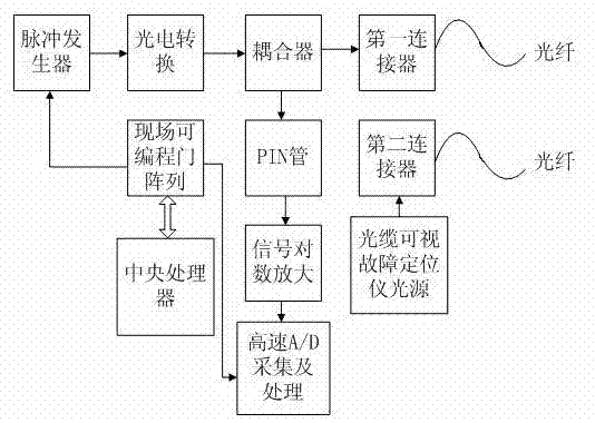
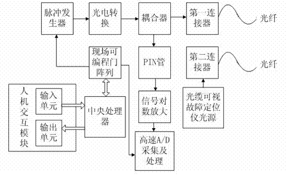
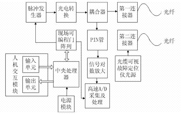
[0040] Such as figure 1As shown, this example provides an optical line comprehensive test system, including:
[0041] CPU;
[0042] a field programmable gate array controlled by the central processing unit;
[0043] a pulse generator controlled by said field programmable gate array;
[0044] Photoelectric conversion, controlled by the pulse generator to send out corresponding light signals;
[0045] a coupler for receiving the optical signal emitted by the photoelectric conversion;
[0046] PIN tube, accepting the optical signal transmitted by the coupler;
[0047] Signal logarithmic amplification, amplifying the electrical signal output by the PIN tube;
[0048] High-speed A / D acquisition and processing, controlled by the field programmable gate array, processing the electrical signal logarithmically amplified and outputted by the signal;
[0049] a first connector, respectively connected to the coupler and the optical fiber;
[0050] Optical cable visual fault locator...
Embodiment 2
[0057] The difference from Embodiment 1 is that the pulse generator in this embodiment uses a pulsed laser to emit pulsed laser signals.
[0058] Wherein, the pulse generator adopts a pulse laser to emit a pulse laser signal, and the pulse generator is mainly responsible for driving the pulse laser to emit a pulse laser signal of a corresponding width, and injecting the optical signal into the optical fiber to be tested through a coupler; Width affects the dynamic range and distance resolution of optical time domain reflectometer (OTDR). During the measurement, according to the length of the optical fiber under test and the test accuracy requirements, an appropriate pulse width is selected to obtain satisfactory measurement results; the optical time domain reflectometer (OTDR) light source and the stable light source use the same pulse laser.
[0059] This example further adopts the above-mentioned technical features, and its advantage is that the stable light source, optical ...
Embodiment 3
[0061] The difference from Embodiment 1 is that the coupler in this embodiment adopts a Y-type optical fiber splitter.
[0062] Wherein, the coupler includes an optical fiber splitter, and the optical fiber splitter adopts a Y-shaped optical fiber splitter, which is an optical fiber splitter that splits an optical signal from one optical fiber to multiple optical fibers.
[0063] This example further adopts the above-mentioned technical features, and its advantage is that the stable light source, optical power meter and optical time domain reflectometer (OTDR) use the same optical path and share the same optical interface, and can complete multi-indicator testing with one access, which solves the problem of It solves the problem of its portability, can greatly reduce the total cost of ownership of the system, and avoids too many operations on the optical fiber active interface. On this basis, the coupler adopts a Y-type optical fiber splitter, which can well control The distri...
PUM
 Abstract
Description
Claims
Application Information
 - R&D
- Intellectual Property
- Life Sciences
- Materials
- Tech Scout
- Unparalleled Data Quality
- Higher Quality Content
- 60% Fewer Hallucinations
Browse by: Latest US Patents, China's latest patents, Technical Efficacy Thesaurus, Application Domain, Technology Topic, Popular Technical Reports.
© 2025 PatSnap. All rights reserved.Legal|Privacy policy|Modern Slavery Act Transparency Statement|Sitemap|About US| Contact US: help@patsnap.com


