Inspection method of valve group and valve group unit and valve group unit

A valve group and valve core technology, applied in valve details, multi-port valves, valve devices, etc., can solve problems such as increased energy consumption, increased cost, and reduced productivity, to improve production efficiency, simplify piping structure, and seek miniaturization. Effect

Active Publication Date: 2015-09-16
MITSUBISHI ELECTRIC CORP
View PDF5 Cites 0 Cited by
  • Summary
  • Abstract
  • Description
  • Claims
  • Application Information

AI Technical Summary

Problems solved by technology

However, since the heat exchange between the refrigerant and the water is carried out in the outdoor unit, and the water is sent to the indoor unit, the water transfer power becomes very large, which increases energy consumption.
In addition, in the case of supplying both cooling energy and heating energy using water or the like, it is necessary to connect a plurality of pipes, which takes a lot of labor, time, and expense required for installation work.
When storing connecting piping, valves, and heat exchangers on the device side in advance to simplify on-site piping work, the device for storing piping and valves becomes very large, resulting in increased cost and reduced productivity

Method used


Image

  • Inspection method of valve group and valve group unit and valve group unit
  • Inspection method of valve group and valve group unit and valve group unit
  • Inspection method of valve group and valve group unit and valve group unit

Examples


Embodiment approach 1

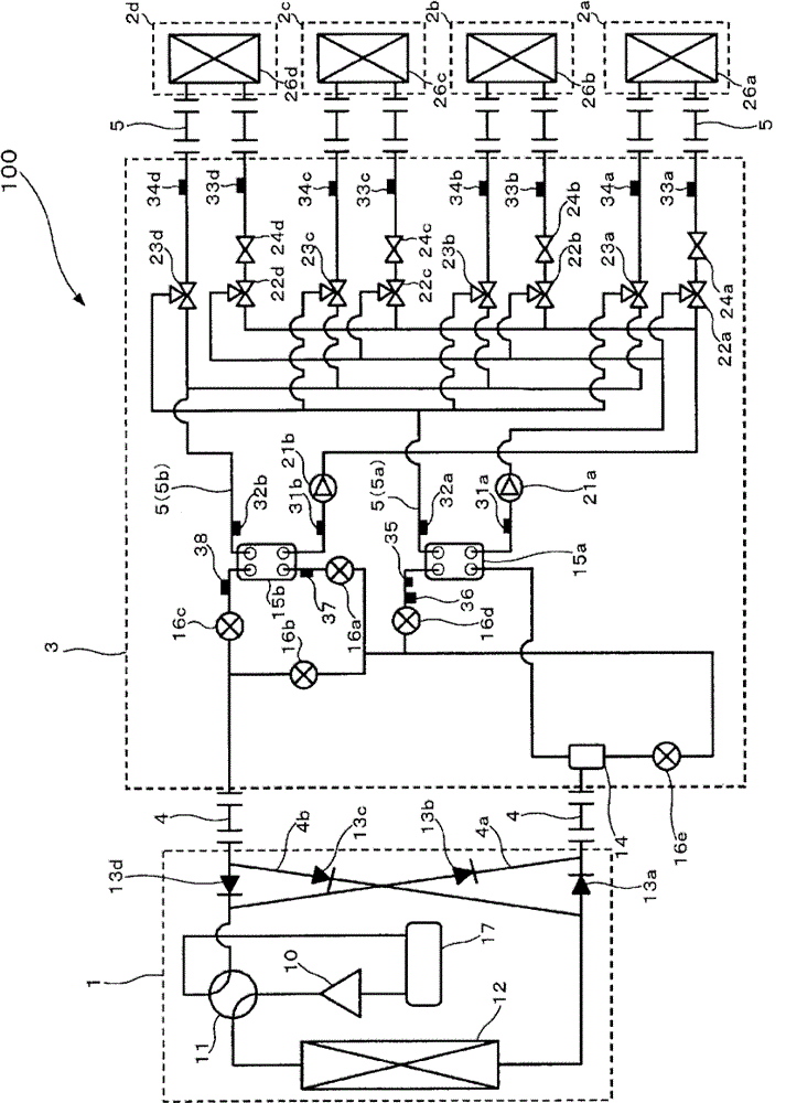
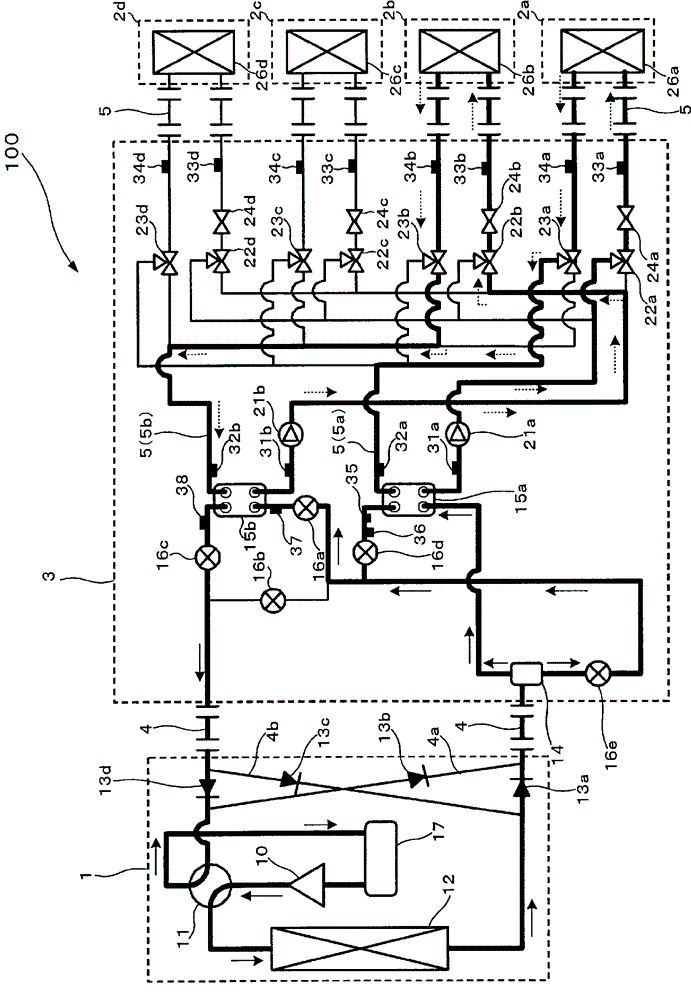
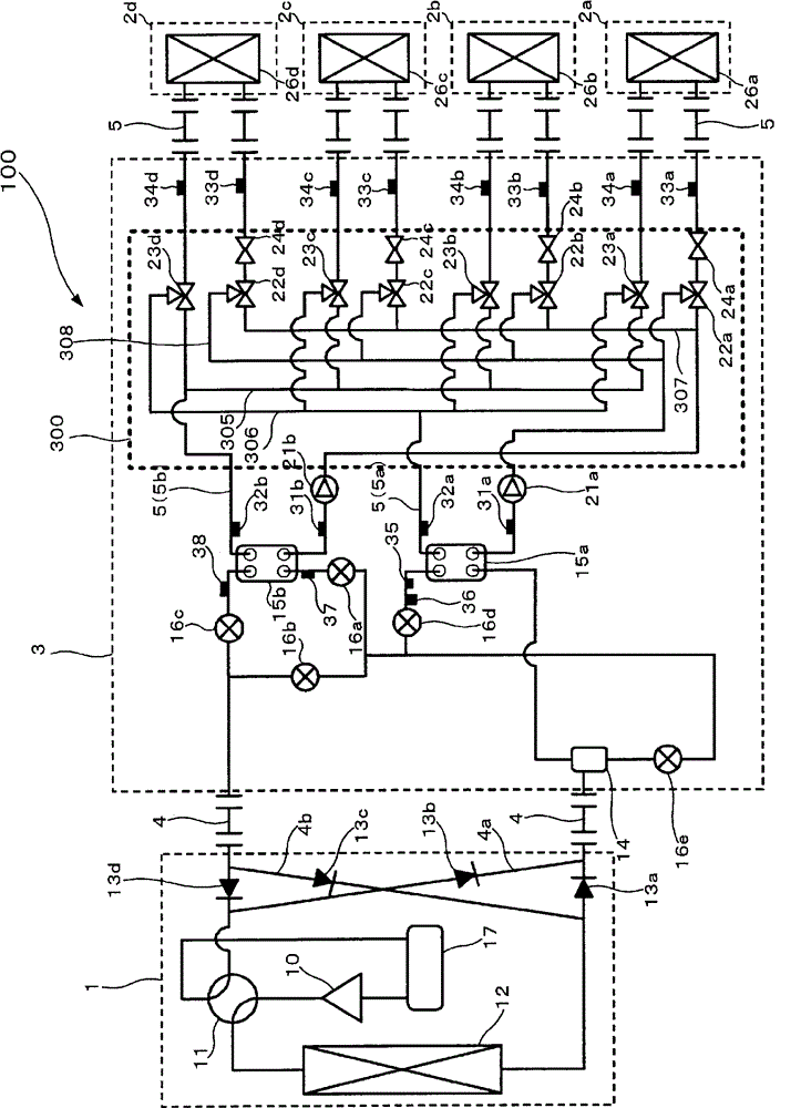
[0036] figure 1 It is a schematic circuit diagram showing the structure of the air-conditioning apparatus 100 equipped with the valve block unit 300 in Embodiment 1 of this invention. according to figure 1 The detailed configuration of the air-conditioning apparatus 100 will be described. Such as figure 1 As shown, the outdoor unit 1 and the heat medium relay unit 3 are connected via the first heat exchanger related to heat medium 15a and the second heat exchanger related to heat medium 15b, and the heat medium relay unit 3 and the indoor unit 2 are also connected via the first heat medium room The heat exchanger 15a and the second heat exchanger related to heat medium 15b are connected. Hereinafter, the configuration and function of each component device provided in the air-conditioning apparatus 100 will be described.

[0037] [Outdoor unit 1]

[0038] The outdoor unit 1 accommodates a compressor 10 connected in series by a refrigerant pipe 4 , a four-way valve 11 as a ...

Embodiment approach 2

[0124] Figure 13 It is a vertical cross-sectional view schematically showing the cross-sectional structure of the valve group 351 constituting the valve group unit 300a according to Embodiment 2 of the present invention. according to Figure 13 At the same time, the structure of the valve group 351 and the flow of heat medium will be described. In addition, in Embodiment 2, the difference from Embodiment 1 will be mainly described, and the same reference numerals will be attached to the same parts as Embodiment 1, and description will be omitted.

[0125] In Embodiment 1, the heat medium flow switching device 22 and the heat medium flow switching device 23 pass through respective spools (spool 304a, spool 304b) and spool rotation mechanisms (spool rotation mechanism 309, valve core rotation mechanism 310) to switch flow paths. It can be seen from the functions of the heat medium flow switching device 22 and the heat medium flow switching device 23 that their operations are...


PUM


Abstract

Provided are a valve block and a valve block unit which allow simplification and miniaturization of a pipe arrangement. A valve block 350 according to the present invention includes at least one flow direction switching means 22 including a valve body 304a, the means selectively switching between conductions of a fluid (heat medium), a first pipe (heating outward-flow main pipe 308) and a second pipe (cooling outward-flow main pipe 307), switched by the flow direction switching means 22, allowing the fluid to be conveyed therethrough, and a third pipe (first branch pipe 3) that selectively communicates with the first pipe or the second pipe, the flow direction switching means, the first pipe, the second pipe, and the third pipe being connected to each other.

Description

technical field [0001] The present invention relates to a valve group having a plurality of pipes and at least one flow switching device, a valve group unit formed by connecting a plurality of the valve groups, and a method for inspecting the valve group unit, and particularly relates to a valve group unit capable of simplifying and miniaturizing the piping structure Valve blocks and valve block units. Background technique [0002] At present, there are multi-type air conditioners for large buildings using an air-conditioning device that circulates a refrigerant between an outdoor unit that is a heat source unit disposed outdoors and an indoor unit disposed indoors. Cooling energy or heating energy is sent to an area to be air-conditioned such as a room, and a cooling operation or a heating operation is performed (for example, refer to Patent Document 1). As refrigerants used in such air conditioners, for example, HFC refrigerants are often used. In addition, in recent yea...

Claims


Application Information

Patent Timeline
Patent Type & Authority Patents(China)
IPC IPC(8): F16K27/00
CPCF25B41/003F16K11/085F16K11/22Y10T137/86493F25B13/00F25B2313/02741F16K27/003F25B2313/0272F25B25/005F25B2313/0231F25B41/42
Inventor 森本裕之山下浩司林田胜彦中尾博人本村祐治若本慎一
Owner MITSUBISHI ELECTRIC CORP
Why Eureka
Try Eureka