

Multilayer fluidized bed gasification furnace
A fluidized bed gasifier and a multi-layer fluidized bed technology, which is applied in the field of gasifiers, can solve the problems of prolonging the residence time of pulverized coal, uneven heating of the solid phase, and large energy consumption of gasification reaction, and achieves the average length of time. Residence time, high solid-phase processing depth, and the effect of improving carbon conversion
- Summary
- Abstract
- Description
- Claims
- Application Information
AI Technical Summary
Problems solved by technology
Method used
Image

Examples
Embodiment 1
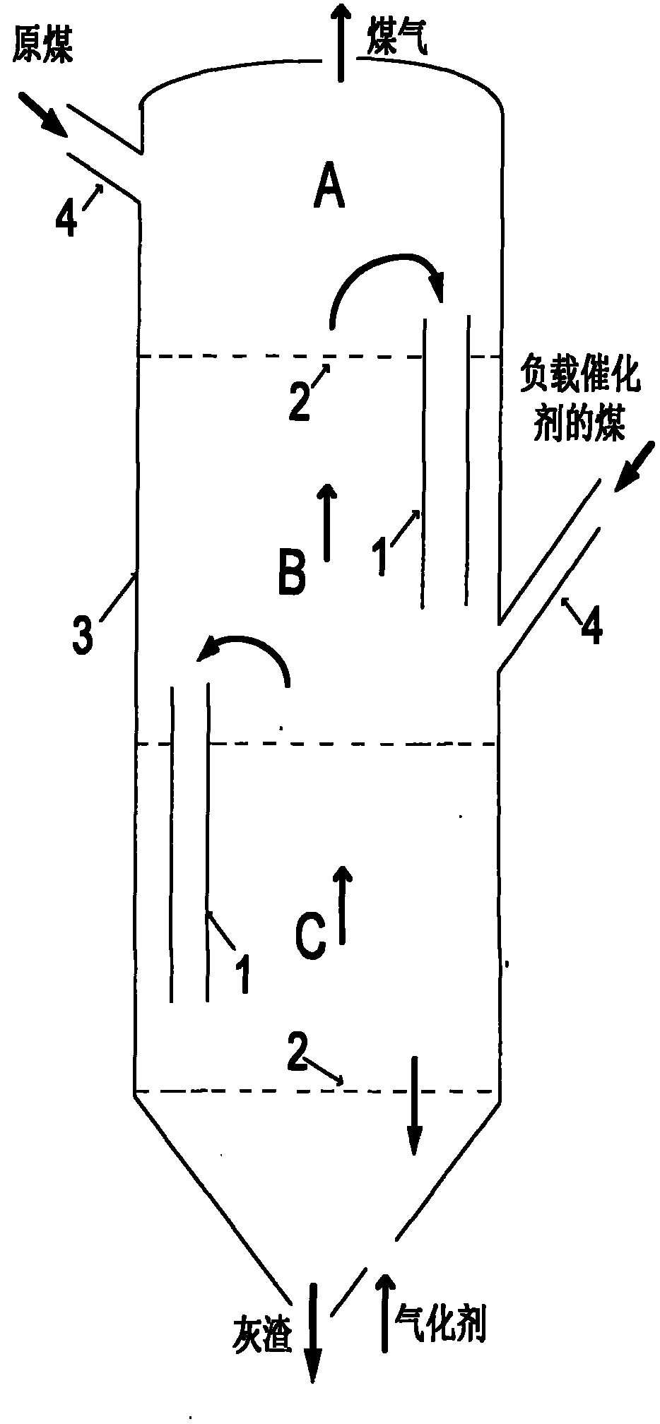
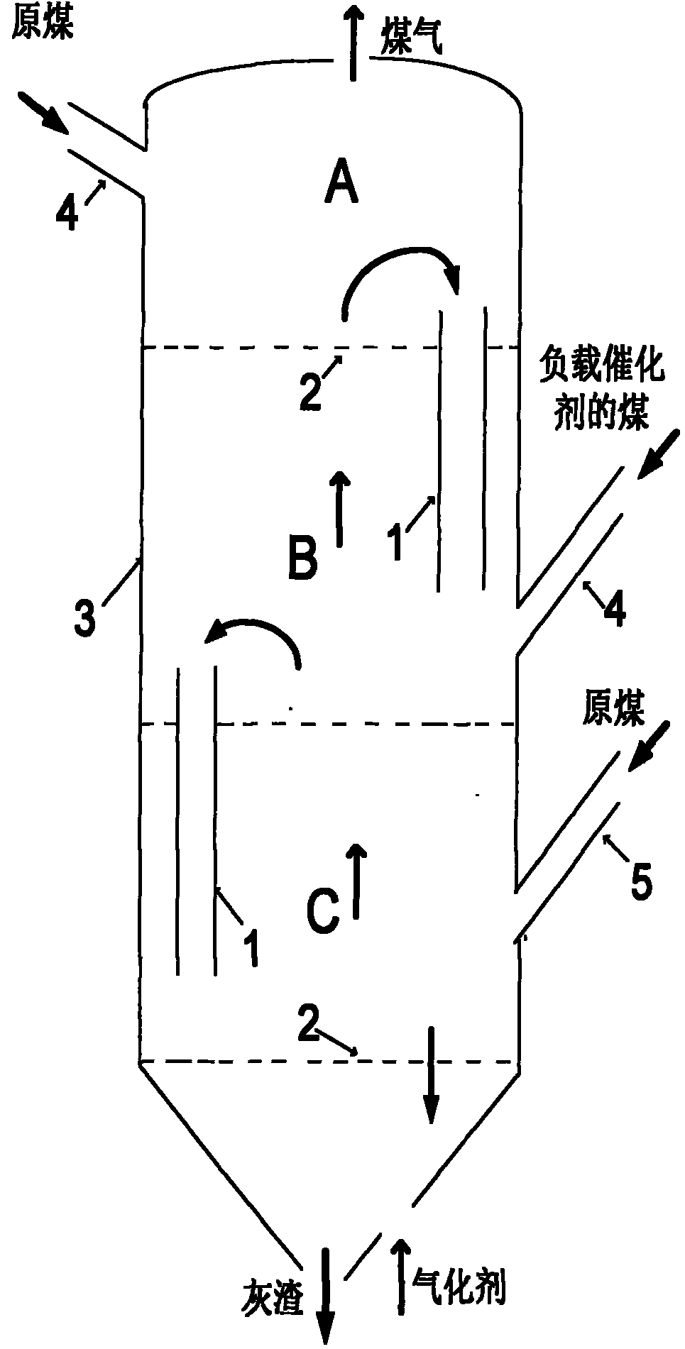
[0101] see figure 2 , in the structure figure 1 If the heat generated by the gasification of residues alone is difficult to meet the temperature requirements for catalytic gasification, a further step can be installed on the side wall of the furnace body 3 of the lowest layer C (residue gasification zone) of the multi-layer fluidized bed. Feed port 5, through which a small amount of raw coal is fed into the residue gasification zone, and the combustion of the small amount of raw coal in the lowest layer C (residue gasification zone) can provide auxiliary energy to meet the temperature requirements for catalytic gasification.
Embodiment 2
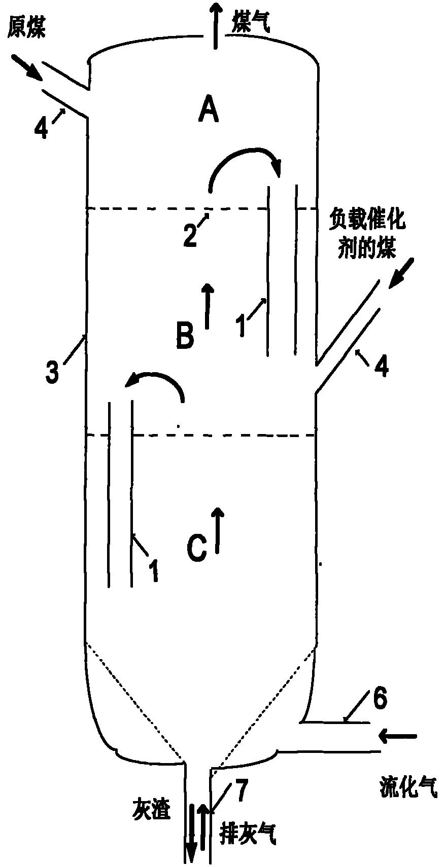
[0103] see image 3 , in the structure figure 1 In order to meet the needs of ash discharge or process operation conditions, the distribution plate of the lowest layer C of the multi-layer fluidized bed can be replaced, and the funnel-shaped distribution plate can be used to control the ash discharge gas velocity and flow through the air inlets 6 and 7 respectively. gasification speed.
Embodiment 3
[0105] see Figure 4 , in the structure figure 1 In order to avoid the reverse series of gas, realize the continuous and stable overflow between the beds, and at the same time facilitate the control of the overflow flow of the material, other forms of overflow devices can be used, such as plug-type overflow devices with mechanical transmission devices . Adjust the position of the plug 8 through the mechanical transmission device, change the direction of the gas and the size of the cross-section of the discharge port, and realize a smooth overflow.
[0106] in combination Figure 1-4 In the various embodiments shown and described above, the scale settings in the figures can be improved (that is, the scale settings after improvement are different from those in the Figure 1-4 ratio shown in ), so that the shortest distance between the upper end of the first overflow device and the inner wall of the gasifier shell is between 1 / 5 and 1 / 2 times the inner diameter of the gasifie...
PUM
 Abstract
Description
Claims
Application Information