Automatic press-mounting method and equipment for optical transceiver assembling member

A technology for optical transceivers and assemblies, which is applied in the field of automatic press-fitting methods and equipment for optical communication devices, can solve the problems of high cost, high labor intensity, and low efficiency, and achieve recycling, saving manpower and material resources, and production efficiency high effect

Active Publication Date: 2012-04-04
FINETOP SCI &TECH
View PDF7 Cites 12 Cited by
  • Summary
  • Abstract
  • Description
  • Claims
  • Application Information

AI Technical Summary

Problems solved by technology

[0005] The above-mentioned devices all have a common shortcoming: in the process of pressing, only the dynamic pressure is displayed, and the pressure value when pressing to a certain position cannot be accurately understood; it is impossible to judge whether the pressing force of the product is qualified; After the press-fitting is completed, the display of dynamic pressure disappears and no record is left
The automatic control press-fitting equipment solves the problem of pressure control, but the parts and press-fitting tooling still have to be placed and picked up by hand during product press-fitting, and automatic control cannot be realized. At the same time, it cannot automatically identify whether the product is qualified or not, and it still needs to be re-tested. Resulting in high labor intensity, low efficiency and high cost

Method used


Image

  • Automatic press-mounting method and equipment for optical transceiver assembling member
  • Automatic press-mounting method and equipment for optical transceiver assembling member
  • Automatic press-mounting method and equipment for optical transceiver assembling member

Examples


Embodiment 2

[0070] Embodiment 2, the automatic press-fitting equipment among the present invention, wherein the number of stations is 8, makes the automatic press-fit method of the optical transceiver assembly of the present invention, and it is similar to Embodiment 1, and its difference is: in Between step C and step E, step D is required: after station one 1 completes step A, the working turntable 9 rotates counterclockwise, and turns to station five 5, and the above working turntable 9 is indexed counterclockwise each time The angle of rotation is 45°.

[0071] The automatic press-fitting method of the optical transceiver assembly of the present invention is specifically: the synchronous motor 21 fixed on the frame 17 cooperates with the gear 20 on the main shaft 23 through the cam 22, so that the working turntable rotates in 9 degrees. Work turntable 9 directions of rotation are counterclockwise, because of 8 stations on the work turntable 9, then there are 8 teeth on 20 gears. When...


PUM


Abstract

The invention discloses an automatic press-mounting method and equipment for an optical transceiver assembling member and belongs to the technical field of manufacturing optical communication devices. The automatic press-mounting method for the optical transceiver assembling member disclosed by the invention comprises the following steps of: placing a metal tail-handle, covering the upper cover of a press-mounting tool, placing a ceramic ferrule, applying pressure to the upper cover of the press-mounting tool to form a tail-handle assembly, taking away the upper cover of the press-mounting tool, screening unqualified products with poor pressure-bearing capability and skimming off products with qualified sizes and products with ultra-poor sizes. The invention further discloses automatic press-mounting equipment for the optical transceiver assembling member. According to the automatic press-mounting equipment for the optical transceiver assembling member disclosed by the invention, the automatic feeding during the press-mounting process and the full-automatic operation during the press-mounting process are solved; whether the force is out of limits and the press-mounting matching size is qualified during the press-mounting process can be judged, and the quality characteristics of the products can be selected automatically; the structure is simple and the operation is simple and convenient; the automatic operation of the complete device is realized, and the reduction of labor force, the increasing of efficiency and the reduction of cost are achieved.

Description

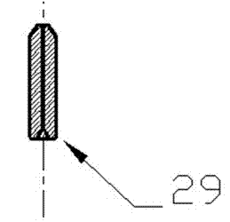
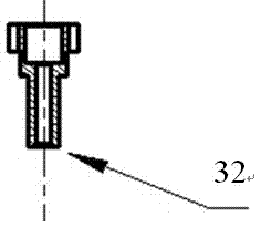
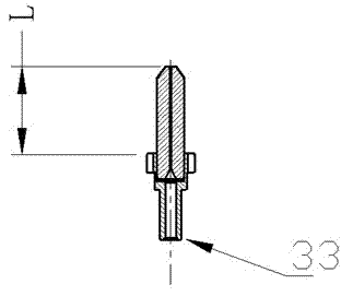
technical field [0001] The invention relates to the technical field of manufacturing optical communication devices, in particular to an automatic press-fitting method and equipment for optical communication devices. Background technique [0002] During the assembly process of the core component of the optical transceiver module, the optical transceiver involves some press-fitting processes, such as: pressing the standard ceramic ferrule into the metal tail handle, pressing the short ceramic ferrule into the metal stopper, Press-fit stoppers to ferrule sleeves, press-fit chips to metal housings, etc. like Figure 1 to Figure 3 As shown, the ceramic ferrule 29 is pressed into the metal tail handle 30 to form the tail handle assembly 33 . For the above-mentioned press-fitting process, the press-fitting equipment currently used are: [0003] 1. Manual pressing machine, as follows Figure 4 As shown, when working, the handle 51 is manually pulled, and the pressure head 52 of t...

Claims


Application Information

Patent Timeline
Patent Type & Authority Applications(China)
IPC IPC(8): G02B6/42B23P21/00
Inventor 胡永忠罗祠富
Owner FINETOP SCI &TECH
Why Eureka
Try Eureka