Single-vortex double-pressure turbocharging system

A turbocharging system and turbine technology, applied to the charging system, adding non-fuel substances to the fuel, internal combustion piston engines, etc., can solve the problems such as the inability to adjust the matching relationship between the turbine and the compressor, and the limitation of the flow range of the compressor, etc., to achieve Effects of preventing surge, simplifying control strategy, and improving dynamic performance

Inactive Publication Date: 2012-04-18
SHANGHAI JIAO TONG UNIV
View PDF5 Cites 4 Cited by
  • Summary
  • Abstract
  • Description
  • Claims
  • Application Information

AI Technical Summary

Problems solved by technology

[0003] After searching the existing technical literature, it is found that the Chinese patent application number is 200510025774.0, and the patent name is: large and small turbocharged series-parallel adjustable booster system. , sequential turbocharging and two-stage turbocharging, so that the range of the equivalent flow area of ​​the turbine is wider; but the flow range of the compressor is limited
Chinese patent application number 200710144757.8, patent name: adjustable sequential load turbocharging system, in the specific implementation of this patented technology, a single turbocharging, two parallel turbocharging, intake and exhaust bypassing are realized through the bypass method Turbocharging, high working condition bleed turbocharging, expands the operating range of the turbocharged diesel engine and improves the performance of the turbocharged diesel engine in the full range of working conditions; but this invention cannot adjust the relationship between the turbine and the compressor matching relationship

Method used


Image

  • Single-vortex double-pressure turbocharging system
  • Single-vortex double-pressure turbocharging system

Examples


Embodiment

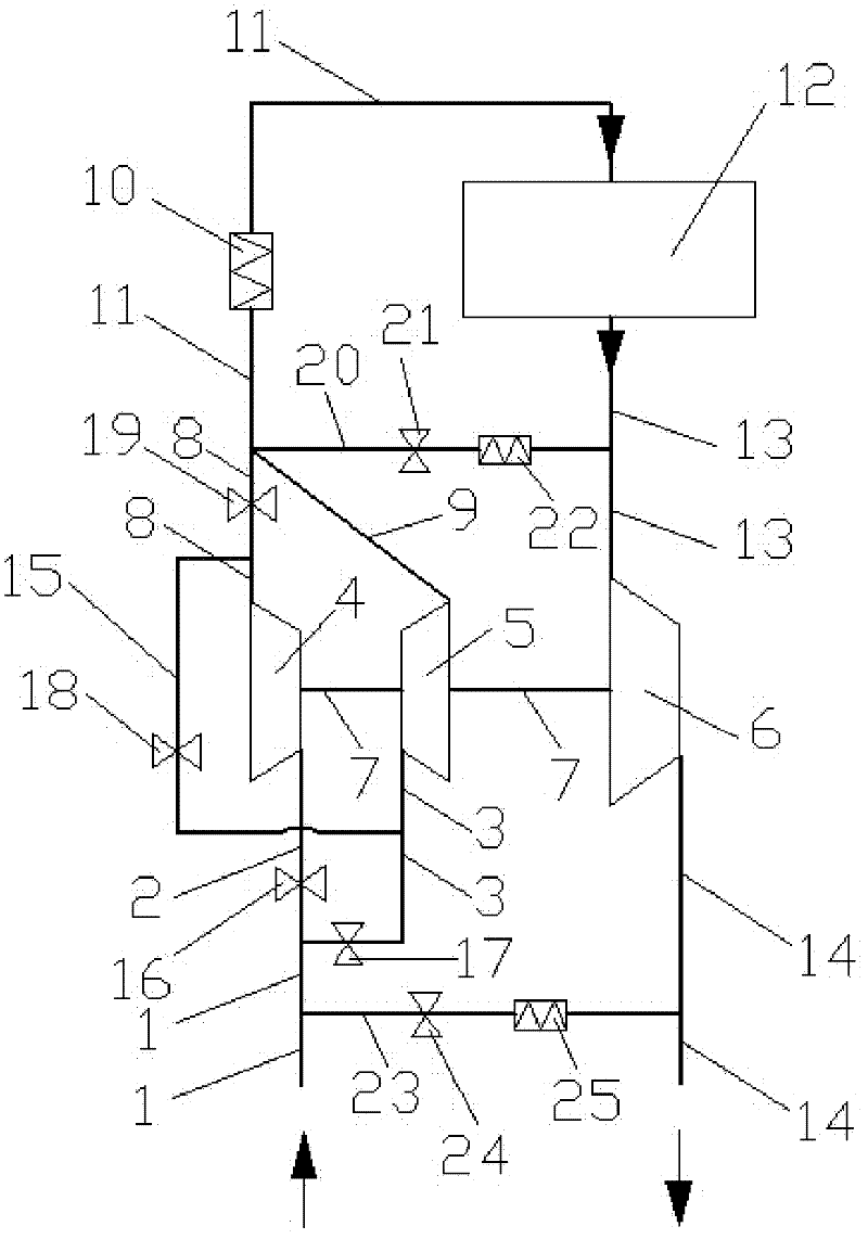
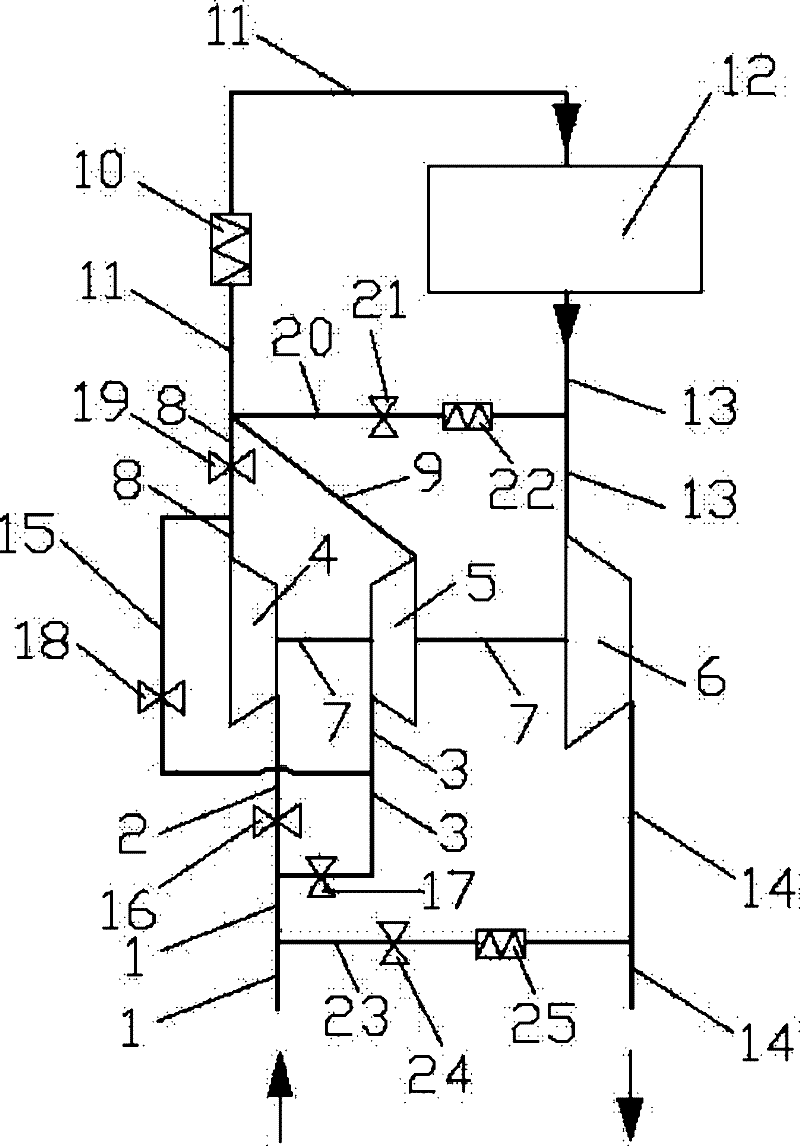
[0014] like figure 1 As shown, the present invention comprises: intake pipe 1, intercooler 10, intake manifold 11, engine 12, exhaust manifold 13, turbine 6, exhaust pipe 14, first compressor intake pipe 2, second compressor intake Air pipe 3, first compressor 4, second compressor 5, connecting shaft 7, first compressor outlet pipe 8, second compressor outlet pipe 9, connecting pipe 15, first control valve 16, second control valve 17 , the third control valve 18, the fourth control valve 19, the high-pressure connecting pipe 20, the high-pressure control valve 21, the high-pressure intercooler 22, the low-pressure connecting pipe 23, the low-pressure control valve 24 and the low-pressure intercooler 25, and the intercooler 10 is installed On the air intake main pipe 11, the air outlet of the air intake main pipe 11 links to each other with the air intake of the engine 12, the air outlet of the engine 12 links to each other with the air intake of the exhaust main pipe 13, and t...


PUM


Abstract

The invention relates to a single-vortex double-pressure turbocharging system in the technical field of internal combustion engines. The system comprises an air inlet pipe, a main air inlet pipe, an engine, an exhaust pipe, a main exhaust pipe, a turbine, a first air compressor, a second air compressor, a connecting shaft, a connecting pipe and control valves, wherein the first air compressor, the second air compressor and the turbine are coaxially connected through the connecting shaft; a first control valve is arranged on a first air compressor air inlet pipe; a second control valve is arranged on a second air compressor air inlet pipe; a third control valve is arranged on the connecting pipe; a fourth control valve is arranged on a first air compressor air outlet pipe; a high-pressure control valve is arranged on a high-pressure connecting pipe; and a low-pressure control valve is arranged on a low-pressure connecting pipe. Three working modes of a single air compressor, double aircompressors connected in parallel and double air compressors connected in series and exhaust gas recirculation in the three working modes can be realized by adjusting the opening and closing of different control valves. The invention is reasonable in design, simple in control strategy and suitable for the turbocharging system with various cylinder numbers.

Description

technical field [0001] The invention relates to a turbocharging system in the field of internal combustion engines, in particular to a single-scroll dual-pressure turbocharging system capable of realizing compressors working in series and parallel. Background technique [0002] In the face of increasingly severe environmental and energy crises, increasing power density, reducing fuel consumption and reducing emissions have become the main directions for the development of internal combustion engines. Turbocharging is not only the most effective way to strengthen the internal combustion engine, but also achieves the purpose of reducing fuel consumption and reducing emissions at the same time, which has become an indispensable technical means of modern internal combustion engine technology. However, due to the influence of the flow characteristics of the turbocharger compressor, for the traditional single-scroll single-pressure system, the compressor can only work in a relativ...

Claims


Application Information

Patent Timeline
Patent Type & Authority Applications(China)
IPC IPC(8): F02B37/12F02B37/007F02B37/013F02M25/07F02B29/04F02M26/08
CPCY02T10/146Y02T10/121Y02T10/144Y02T10/12
Inventor 徐敏邓康耀桂勇石磊
Owner SHANGHAI JIAO TONG UNIV
Why Eureka
Try Eureka