High efficient boiler

A high-efficiency boiler technology, applied in steam boilers, boiler smoke tubes/fire tubes, boiler drums/box-type headers, etc., can solve low thermal efficiency, difficult to remove carbon and ash deposits in fire tubes, and boiler exhaust Smoke heat loss and other issues

Inactive Publication Date: 2012-04-18
蒋恩良
View PDF6 Cites 3 Cited by
  • Summary
  • Abstract
  • Description
  • Claims
  • Application Information

AI Technical Summary

Problems solved by technology

The vertical horizontal water tube boiler has the advantages of good ventilation and compact structure, but it also has its disadvantages. The bottom horizontal water tube is in a local high-temperature environment, and the thermal expansion stress will always negatively affect the entire heating surface of the boiler during the entire combustion state. In addition, Single-pass heat-absorbing structure boilers have a lot of exhaust heat loss, and the formation and accumulation of scale and ash on the heating surface of the boiler will inevitably reduce the heat transfer rate of the entire heat-absorbing structure
[0003] The disadvantage of the traditional bent fire tube boiler is that although the bent fire tube can absorb the thermal expansion stress, a large thermal expansion stress still exists. The biggest problem of the traditional bent fire tube boiler is that the carbon and ash deposits in the fire tube are difficult to remove easily , especially for civil small-capacity boilers, there is no soot-blowing condition, so large-diameter seamless pipes have to be used as pyrotechnic pipes, so that even if the phenomenon of ash plugging is alleviated a little, the low thermal efficiency is a fact that has to be faced

Method used


Image

  • High efficient boiler
  • High efficient boiler
  • High efficient boiler

Examples


Embodiment Construction

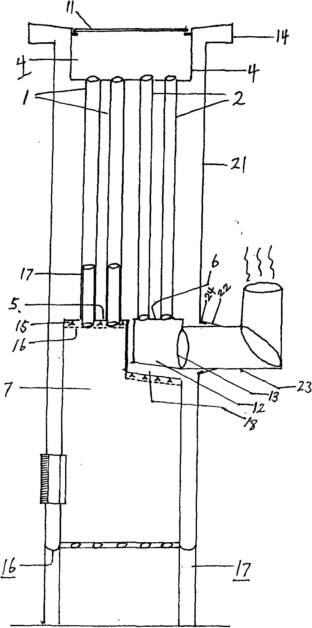
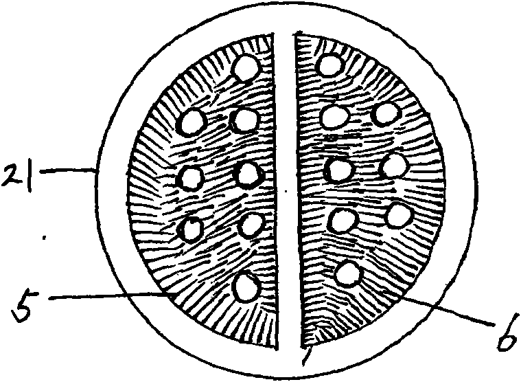
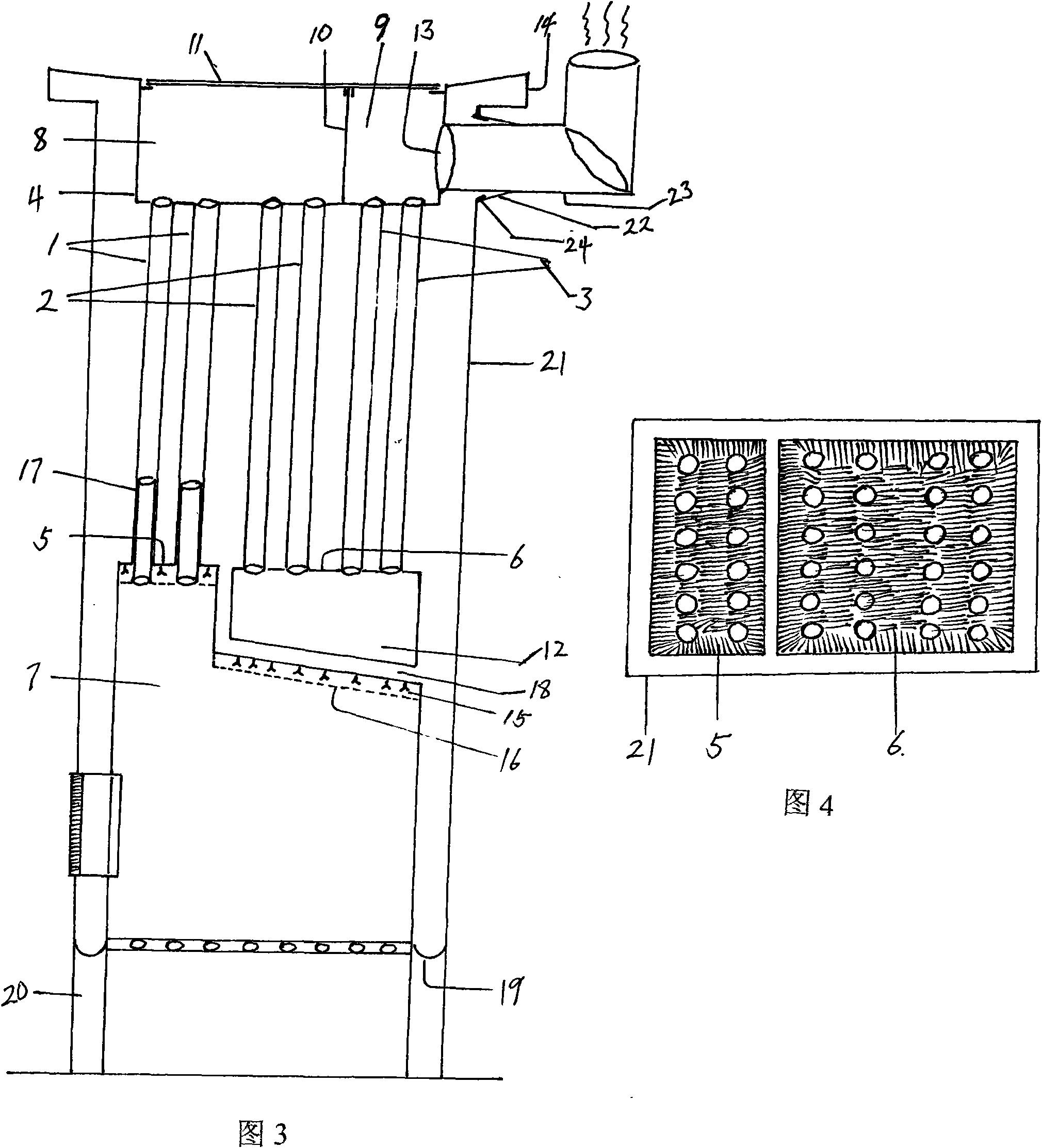
[0015] figure 1 The pyrotechnic tube bundles in can be divided into high-temperature flue gas first-pass pyrotechnic tube bundles (1) and high-temperature flue gas second-pass pyrotechnic tube bundles (2), which are located between the upper tube sheet (4) and the lower tube sheet, and the upper tube sheet is The tub-shaped structure tube plate, and the lower tube plate is divided into the lower tube plate (5) of the first-stroke pyrotechnic tube bundle and the lower tube plate (6) of the second-stroke pyrotechnic tube bundle. The lower tube plate of the first-pass pyrotechnic tube bundle is also the high-position furnace roof of the boiler, below which is the combustion chamber, and under the lower tube plate of the second-pass pyrotechnic tube bundle is the lower smoke chamber, which is a water-cooled structure. The lower smoke chamber is located at a low position above the furnace roof. The pyrotechnic tube bundle of the heat-absorbing structure is composed of several vert...


PUM


Abstract

The invention relates to a high efficient fire standpipe boiler, which generally consists of a boiler housing, a boiler flue, a boiler flue top, an internal upper smoke chamber, a smoke-fire standpipe, a lower smoke chamber, a boiler base and the like. A smoke-fire standpipe bundle is orderly arranged between an upper pipe plate and a lower pipe plate, the smoke-fire standpipe bundle consists of a plurality of metal standpipes, the upper pipe plate and the internal upper smoke chamber are arranged above the smoke-fire pipe bundle, a sealing cover plate which can be opened and is provided with a heat preserving layer is arranged above the upper smoke chamber, a combustion chamber is arranged below the lower pipe plate of a first travel-route smoke-fire pipe bundle, the lower smoke chamber is arranged below the other travel-route smoke-fire pipe bundles, the orientation and the travel route of the smoke are decided by the existence of separating plates inside the upper and the lower smoke chambers and the quantity of the separating plates, and the boiler can be divided into a two-travel-route heat absorption structure, a three-travel-route heat absorption structure and a multi-travel-route heat absorption structure according to the orientation of the smoke in the smoke-fire pipe bundle. Due to the adoption of the smoke-fire pipe bundle consisting of the multi-travel-route metal standpipes, the accumulated charcoal and the water scale can be convenient to clear, the smoke exhaustion temperature can be effectively reduced, and the boiler heat efficiency can be improved; and due to the solving of the local high temperature and the heat expansion stress problems, the overall durability of the boiler can be improved, and the service life of the boiler can be prolonged.

Description

Technical field: [0001] The invention relates to a high-efficiency boiler, which belongs to the technical field of boilers. Background technique: [0002] The vertical horizontal water tube boiler is the simplest structure among the vertical boilers. It is mainly composed of six parts: the pot shell, the head, the furnace, the furnace roof, the horizontal water pipe and the cupola. The vertical horizontal water tube boiler has the advantages of good ventilation and compact structure, but it also has its disadvantages. The bottom horizontal water tube is in a local high-temperature environment, and the thermal expansion stress will always negatively affect the entire heating surface of the boiler during the entire combustion state. In addition, Single-pass heat-absorbing structure boilers have a lot of exhaust heat loss, and the formation and accumulation of scale and ash on the heating surface of the boiler inevitably reduce the heat transfer rate of the entire heat-absorbin...

Claims


Application Information

Patent Timeline
Patent Type & Authority Applications(China)
IPC IPC(8): F22B31/00F22B37/06F22B37/08F22B37/22F22B37/24F24H1/00F24H9/18
Inventor 蒋恩良
Owner 蒋恩良
Why Eureka
Try Eureka