Interwell parallel resistivity CT (computed tomography) testing method

A testing method and resistivity technology, which is applied in the field of parallel resistivity CT testing between wells, can solve the problems of low data acquisition efficiency, difficult testing of kilometer-deep wells, and limited resolution, so as to achieve large data volume and improve overall well testing. Efficiency and precision, the effect of high precision

Active Publication Date: 2012-04-18
ANHUI UNIV OF SCI & TECH
View PDF5 Cites 25 Cited by
  • Summary
  • Abstract
  • Description
  • Claims
  • Application Information

AI Technical Summary

Problems solved by technology

[0004] The purpose of the present invention is to provide a parallel resistivity CT testing method between wells to solve the problems of low data acquisition efficiency of existing testing methods, difficulty in testing kilometers-deep wells, and limited resolution

Method used


Image

  • Interwell parallel resistivity CT (computed tomography) testing method
  • Interwell parallel resistivity CT (computed tomography) testing method
  • Interwell parallel resistivity CT (computed tomography) testing method

Examples


Embodiment approach

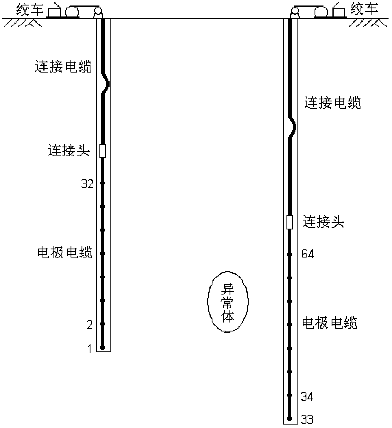
[0029] (1) After the borehole drilling reaches the exploration depth, two boreholes are used to arrange the resistivity CT testing system. Electrodes are arranged at different depths of the wellbore on site according to the needs, and the test section is automatically adjusted and changed by the winch.

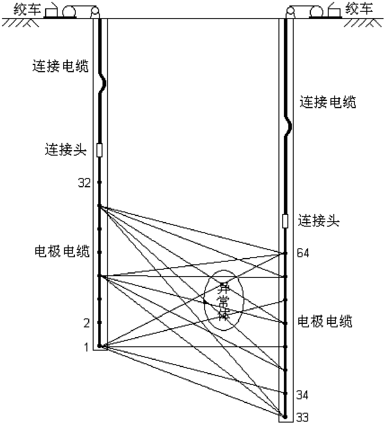
[0030] (2) Conduct cross-well parallel resistivity CT data acquisition for the selected detection area, unify 64 electrodes in two holes into one measurement line, use high-power parallel electrical instrument for data acquisition, and obtain various measurements under different electrode power supply conditions simultaneously The electric field parameters of the electrodes.

[0031](3) Adjust the detection area according to the test needs, and carry out parallel electrical method data acquisition in different test sections. Usually, the data of the two stations need to be overlapped. Calculated based on the electrode distance of 5.0m, each station can control the length of t...

example

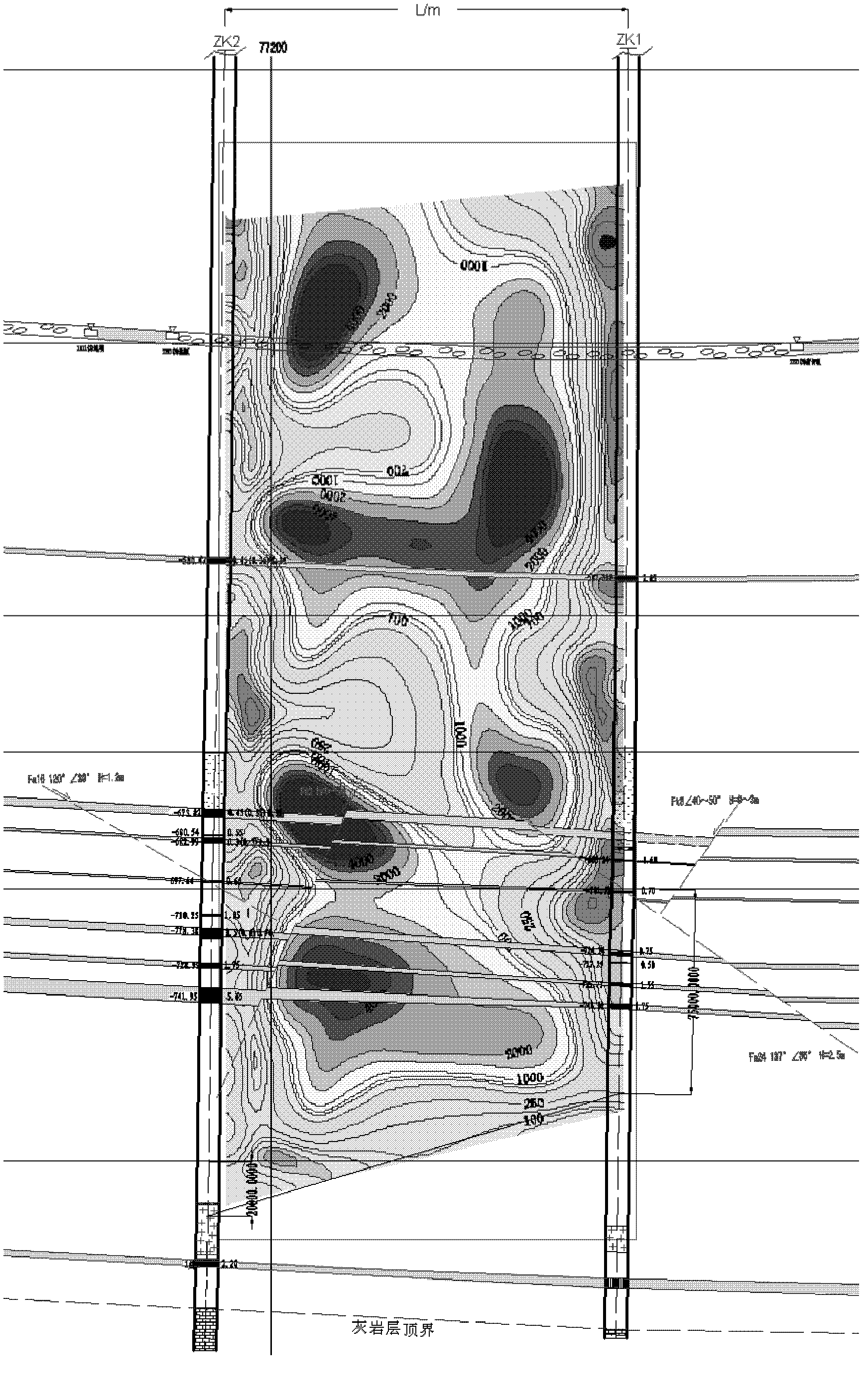
[0035] In order to explore the characteristics of geological anomalies between two boreholes, parallel resistivity CT testing research was carried out on the ground above the working face of a mine in Huainan Mining Group. The maximum depth of the two boreholes is 1160m. The layout of interwell resistivity CT test is as follows: figure 1 As shown, the transmitted ray at the measuring point of station 1 is as follows figure 2 shown. Such as image 3 Shown is the CT inversion calculation section of the entire wellbore resistivity, from which it can be seen that the rock-coal seam combination at the coal seam position is characterized by high resistance, and the layering is more obvious. Coal seams have strong response and poor convergence on interwell resistivity profiles, but single-layer or multi-layer coal seams can be effectively distinguished based on this. The resistivity distribution characteristics between the coal measures and the coal measures, between the Taihui ...


PUM


Abstract

The invention discloses an interwell parallel resistivity CT (computed tomography) testing method which is a geophysical prospecting technology for probing geologic conditions and structural features between drill holes. In the method, through arranging a testing system between every two drilling wells, an interwell measuring line with 64 electrodes is formed; a parallel electrical method data collection technology is utilized to carry out monopole or dipole power supply and test, thus interwell electrical property collected data are obtained, and intewell chromatography data bodies between different electrodes are formed; and an interwell resistivity tomography technology is utilized to carry out resistivity and induced polarization parameter tomography on a test area, thus the terrane and structural feature conditions are further evaluated, and geologic interpretation achievement and recognition are obtained. The testing system can be used for achieving data collection of a 1200m deep well.

Description

technical field [0001] The invention relates to the field of drilling geophysical prospecting, in particular to a parallel resistivity CT testing method between wells. Background technique [0002] Drilling is an important means of obtaining geological data. During geological exploration, drilling can be used to understand the development of various rock formations in underground geological bodies, as well as the distribution characteristics of various geological anomalies such as faults, collapse columns, and fracture zones. Since the drilling is often seen in one hole, there is a lack of comprehensive understanding of the geological conditions on the opposite surface. Therefore, the detection section is constructed by using the spatial conditions between the boreholes, and the cross-well resistivity CT method is used for detection. According to the difference between the resistivity of the rock formations, the geological conditions and abnormal characteristics in the test ...

Claims


Application Information

Patent Timeline
Patent Type & Authority Applications(China)
IPC IPC(8): G01V3/18G01V3/26
Inventor 张平松吴健生吴荣新郭立全胡雄武
Owner ANHUI UNIV OF SCI & TECH
Why Eureka
Try Eureka