Permanent magnet synchronous motor

A technology of permanent magnet synchronous motor and magnetic steel, which is applied in the direction of synchronous machine parts, magnetic circuit rotating parts, magnetic circuit shape/style/structure, etc., which can solve the problem of increasing the difficulty of R&D and design of motor controllers and the difficulty of back electromotive force and other problems, to achieve the effect of easy assembly and production, small cogging torque, and simplified process flow

Inactive Publication Date: 2012-04-18
TIANJIN SANTROLL ELECTRIC SCI & TECH
View PDF8 Cites 20 Cited by
  • Summary
  • Abstract
  • Description
  • Claims
  • Application Information

AI Technical Summary

Problems solved by technology

However, in the existing built-in structure, the back electromotive force waveform is usually a rectangular wave or a trapezoidal wave, and it is difficult to generate a back electromotive force with a sinusoidal waveform, which virtually increases the difficulty in the development and design of the motor controller.

Method used


Image

  • Permanent magnet synchronous motor
  • Permanent magnet synchronous motor
  • Permanent magnet synchronous motor

Examples


Embodiment Construction

[0020] Embodiments of the present invention are described in further detail below in conjunction with the accompanying drawings:

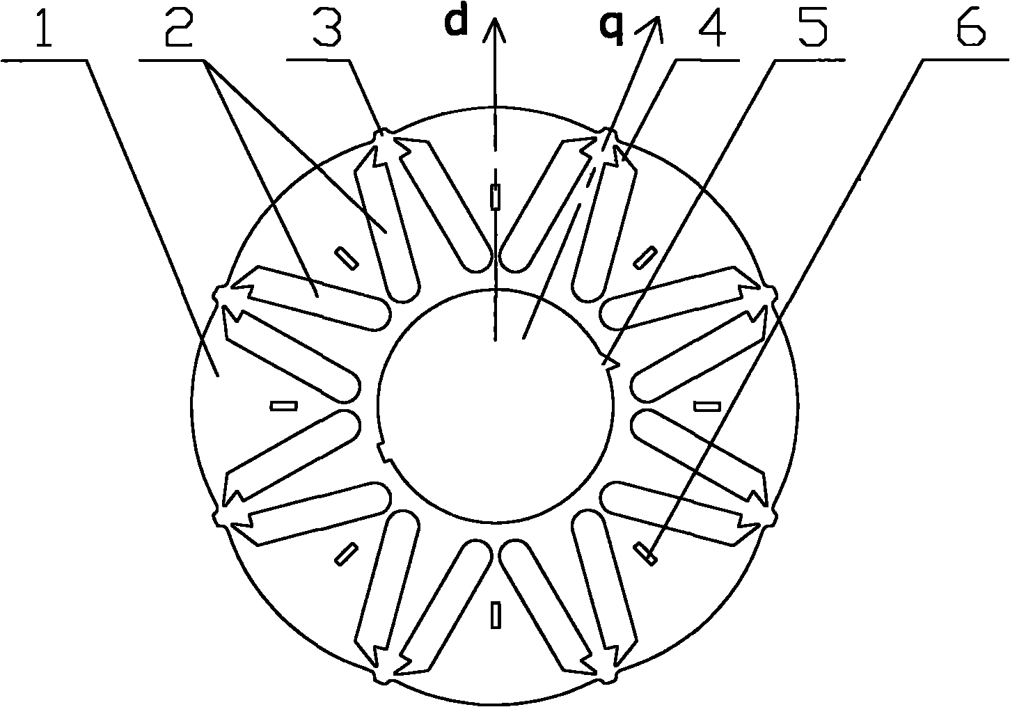
[0021] as attached figure 1 , 1 is the rotor, 2 is the magnetic steel groove, 3 is the protrusion, 4 is the air gap of the magnetic steel groove, 5 is the mark groove, 6 is the positioning riveting point, d is the direct axis of the motor, and q is the quadrature axis of the motor.

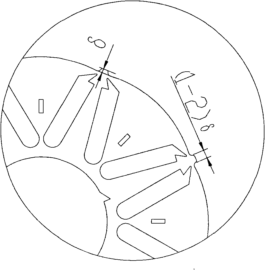
[0022] In a permanent magnet synchronous motor of the present invention, a plurality of magnetic steel slots 2 are evenly distributed on the circumferential surface of the rotor 1, and each magnetic steel slot is independently closed and has no contact with each other. The rotor in this embodiment is provided with 8 poles and 16 magnetic steel slots, two magnetic steel slots are arranged in a V shape, as shown in the figure, the two magnetic steel slots pointed to by 2 are a V-shaped magnetic steel slot group, the V-shaped opening faces the outer circle of the rotor, a...


PUM


Abstract

A purpose of the present invention is providing a permanent magnet synchronous motor rotor structure which has high air gap flux density and is easy to generate back electromotive force with a sine wave. In a permanent magnet synchronous motor, a circumferential surface of the rotor is uniformly provided with a plurality of magnetic steel grooves which are independently enclosed and do not contact mutually. Every two magnetic steel grooves are arranged to form a V shape, an opening of the V shape faces excircle of the rotor, and a tip of the V shape faces a rotor center. Each magnetic steel groove is provided with magnetic steel. In each group of V-shaped magnetic steel grooves, two magnetic steel facing the excircle of the rotor core have a same magnetic pole, and magnetic poles of magnetic steel facing the excircle of the rotor core in two adjacent groups of V-shaped magnetic steel grooves are opposite with the magnetic pole of the two magnetic steel. The excircle of the rotor goes down toward the center with depth delta and smooth transition at a crossing position of axes, which means that air gap width at the crossing position is less than air gap width at a straight axis position by delta. Through improving the rotor, the permanent magnet synchronous motor rotor has high mechanical strength and a large salient pole ratio, and weakened magnetism speed expansion is facilitated.

Description

technical field [0001] The invention relates to the technical field of motors, in particular to a permanent magnet synchronous motor. Background technique [0002] Now commonly used permanent magnet synchronous motor rotor magnetic circuit structure is generally divided into surface type and built-in type. For the surface rotor magnetic circuit structure, the permanent magnets are usually tile-shaped and attached to the outer surface of the rotor core, and the direction in which the permanent magnets provide magnetic flux is radial. Although this kind of rotor magnetic circuit structure is easy to generate back electromotive force with sinusoidal waveform, which is convenient for the research and development and design of the speed-regulating permanent magnet synchronous motor controller, but when running at high speed, due to the large centrifugal force, it is necessary to prevent the permanent magnet from detaching from the rotor core. A non-magnetic sleeve is placed on t...

Claims


Application Information

Patent Timeline
Patent Type & Authority Applications(China)
IPC IPC(8): H02K1/27H02K21/02
Inventor 余国权
Owner TIANJIN SANTROLL ELECTRIC SCI & TECH
Why Eureka
Try Eureka