Current conduction mode switching regulation voltage limiting circuit for current source power supply system of circuit breaker

A technology of power supply system and voltage limiting circuit, which is applied in the direction of converting AC power input to DC power output, electrical components, and output power conversion devices, etc.

Active Publication Date: 2012-04-18
SHANGHAI NOARK ELECTRIC
View PDF5 Cites 10 Cited by
  • Summary
  • Abstract
  • Description
  • Claims
  • Application Information

AI Technical Summary

Problems solved by technology

Its defect is that there is no start-up control circuit, and its MOS tube is always closed during the process of starting up to normal power supply, which brings two major problems
The first problem is that the energy leakage is too large. The reason is: in order to ensure the power supply when the input current of the current transformer is small, the current limiting circuit cannot be set in the power supply circuit, resulting in the comparator U1 and the MOS tube. The energy discharge circuit starts to discharge energy when the input current of the current transformer is still in the normal range, so as to ensure normal power supply
The second problem is that the working voltage is unstable. The reason is that the current in the main circuit of the circuit breaker changes greatly with the change of the load at the user end because there is no starting circuit, that is, the input current of the current transformer varies with the The load changes and fluctuates, which leads to the instability of the working voltage output by the power circuit. Although it can be solved by using a voltage stabilizing circuit, the effect is not satisfactory.
If the secondary coil is disconnected during operation and the current on the secondary side is equal to zero, then the magnetomotive force that acts as demagnetization disappears, while the magnetomotive force on the primary side of the transformer remains unchanged, and the primary current will all become excitation current, which will make The magnetic flux in the iron core increases sharply, and the alternating magnetic flux will induce a high voltage on the secondary coil, and its peak value can reach several thousand or even tens of thousands of volts. Such a high voltage acts on the secondary coil and the secondary circuit. , will seriously threaten the personal safety of the instrument and the operator and the safety of the equipment. In addition, the open circuit of the secondary coil will cause the iron core to heat up severely and burn out the coil insulation or cause the primary high-voltage side to be short-circuited to the ground. The protection may not reflect due to no current. For differential protection and zero-sequence current protection, it may malfunction due to unbalanced current generated when the circuit is open

Method used


Image

  • Current conduction mode switching regulation voltage limiting circuit for current source power supply system of circuit breaker
  • Current conduction mode switching regulation voltage limiting circuit for current source power supply system of circuit breaker
  • Current conduction mode switching regulation voltage limiting circuit for current source power supply system of circuit breaker

Examples


Embodiment Construction

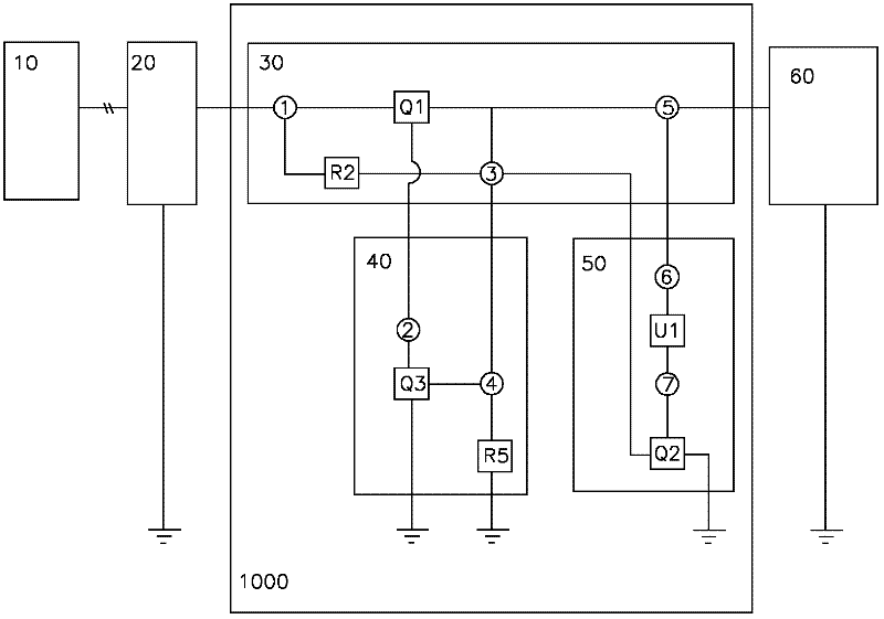
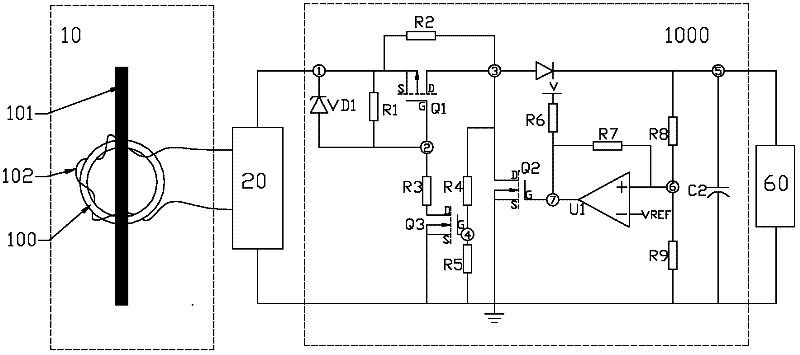
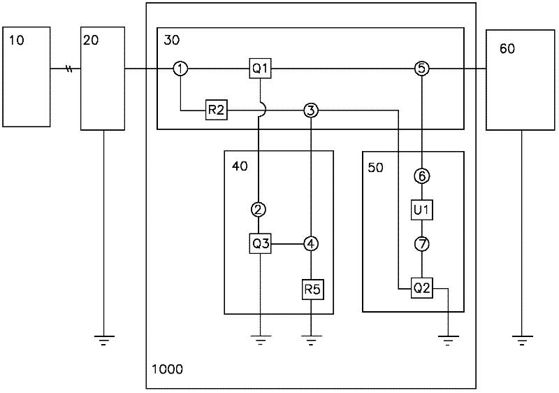
[0019] Below in conjunction with the embodiment shown in the accompanying drawings, the specific implementation of the current continuous switch adjustment voltage limiting circuit of the circuit breaker current source power supply system of the present invention is further described, wherein figure 1 , 2 is the first embodiment of the voltage limiting circuit of the present invention, image 3 , 4 It is the second embodiment, and their difference mainly lies in the connection mode of the second resistor R2. The current continuous switch regulating voltage limiting circuit of the circuit breaker current source power supply system of the present invention is not limited to the description of the following embodiments.

[0020] see Figures 1 to 4 The current continuous switch adjustment voltage limiting circuit of the circuit breaker current source power supply system of the present invention includes a core-through iron core current transformer 10, a fast saturation coil 1...


PUM


Abstract

The invention discloses a current conduction mode switching regulation voltage limiting circuit for a current source power supply system of a circuit breaker. A detection conditioning circuit of the current conduction mode switching regulation voltage limiting circuit comprises a power supply circuit, a starting control circuit, a bleed-off control circuit and nodes (1) to (7). When voltage which is input from the node (3) of the power supply circuit to Q3 through the node (4) of the starting control circuit reaches a starting value of the starting control circuit, the Q3 is switched on, and starting voltage is input to Q1 through the node (2) to switch the Q1 of the power supply circuit on. When the voltage which is input from the node (3) to the Q3 is lower than the starting value of the starting control circuit, the Q3 is switched off, and the voltage which is input from the node (2) to the Q1 by the starting control circuit is converted to be 0 to switch the Q1 off. Then voltage which is input from the node (5) of the power supply circuit to U1 through the node (6) of the bleed-off control circuit is higher than Vre, the voltage of the node (7) of the bleed-off control circuit is higher than a starting value of Q2, the Q2 is switched on and bleeds redundant energy off, and simultaneously, the voltages of the nodes (2 and 3) are both converted to be 0 to switch the Q1 off. When voltage input from the node (5) is lower than the Vre, the voltage of the node (7) is lower than the starting value of the Q2, the Q2 is switched off and stops bleeding the energy off, and simultaneously, the on / off switching of the Q1 is not controlled by the bleed-off control circuit.

Description

technical field [0001] The invention relates to a power supply device for an electronic release of a low-voltage circuit breaker, in particular to a current continuous switch adjustment voltage limiting circuit applied to a current source power supply system of a circuit breaker. Background technique [0002] The various functions of the low-voltage circuit breaker are realized in the form of a release or an accessory. The release is an integral part of the circuit breaker itself. According to the purpose, application occasion and its own volume, the circuit breaker can be equipped with different options. the release device. With the advent of intelligent circuit breakers, the electronic trip unit (ETU) is a kind of intelligent trip unit currently used in circuit breakers. It collects information through core-type current transformers and performs data analysis and processing to control circuit breakers. operating parameters. The current transformer is a commonly used comp...

Claims


Application Information

Patent Timeline
Patent Type & Authority Applications(China)
IPC IPC(8): H02M7/217
Inventor 徐首旗张佳柴爱军徐泽亮
Owner SHANGHAI NOARK ELECTRIC
Why Eureka
Try Eureka