Centrifugal magnetic filter

A magnetic filter and filter net technology, applied in the direction of filtration separation, filtration circuit, separation method, etc., can solve the problems of unable to drain the coolant, high circulation resistance, damage of heat exchange elements, etc., to extend the maintenance interval period, filter High efficiency and improved reliability

Active Publication Date: 2012-04-25
CRRC DALIAN INST CO LTD
View PDF9 Cites 13 Cited by
  • Summary
  • Abstract
  • Description
  • Claims
  • Application Information

AI Technical Summary

Problems solved by technology

Due to the complex structure of the cooling system of a high-power AC drive diesel locomotive, although the system has undergone certain anti-corrosion treatment and a corrosion inhibitor has been added to the cooling liquid, after a period of use, the cooling liquid will be damaged due to corrosion or parts machining. The entry of residual debris and the presence of a large number of impurities
The existence of these impurities has the following hazards. First, it will cause erosion damage to the thin-walled cooling tubes in heat exchange elements such as radiators, intercoolers, and heat exchangers, causing leakage of heat exchange elements; The water in the heat exchange elements such as heat exchangers will cause blockage, which will increase the water resistance of the locomotive cooling system and reduce the water volume, which will affect the heat dissipation performance of the heat exchange elements; For diesel locomotives that are being cooled, due to impurities remaining in the water pipes, the coolant cannot be drained or it takes a long time to drain the coolant, resulting in the freezing of the coolant in the water pipes, which eventually damages the heat exchange elements and affects the safety of the locomotive.
At present, the commonly used filter is a cartridge filter, which has the following disadvantages: relatively large volume, high flow resistance, and inconvenient maintenance

Method used


Image

  • Centrifugal magnetic filter
  • Centrifugal magnetic filter
  • Centrifugal magnetic filter

Examples


Embodiment Construction

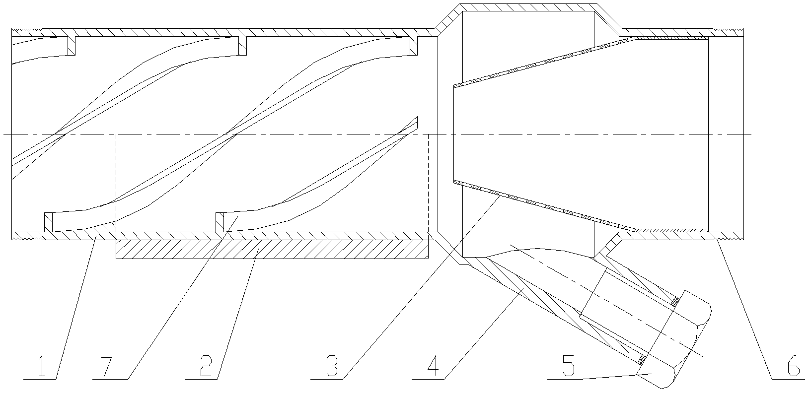
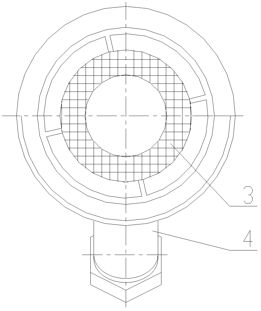
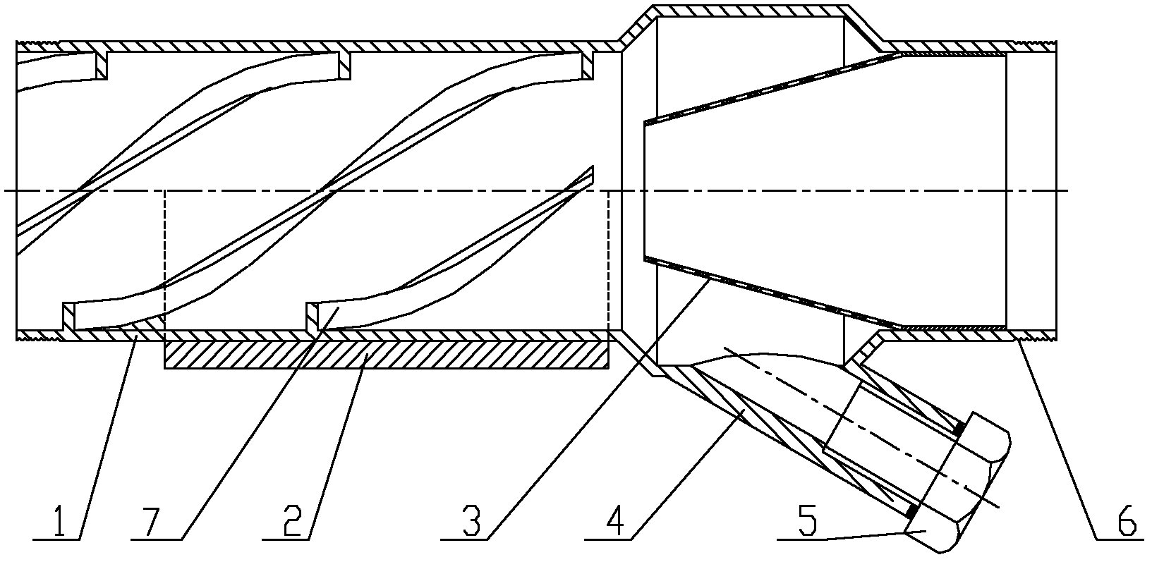
[0015] A novel filter for the cooling system of a high-power diesel locomotive of the present invention is mainly composed of a spiral tube 1, a magnet 2, a truncated conical filter screen 3, a miscellaneous discharge pipe 4, a screw plug 5 and a connecting thread 6 and the like. Such as figure 1 As shown, the direction facing the water flow is the front, and the direction along the water flow is the rear. The front part of the filter body is a spiral tube 1, and the spiral rib 7 extending helically along the axis of the tube body is processed in the wall of the spiral tube 1, and a magnet 2 is attached to the wall of the spiral tube 1, and a filter is installed behind the spiral tube 1. The outer edge of the filter screen and the pipe body fit together, and the pipe body between the outer edge of the filter screen and the spiral tube 1 is provided with a miscellaneous discharge pipe 4.

[0016] The function of the spiral rib 7 is to make the coolant rotate along the axis of ...


PUM


Abstract

The invention relates to a centrifugal magnetic filter. The filter mainly comprises a cylindrical pipe body, wherein a spiral pipe is arranged on the front part of the pipe body; a spiral rib which spirally extends along the axis of the pipe body is arranged on the pipe wall of the spiral pipe; a magnet is attached outside the pipe wall of the spiral pipe; a filter screen is arranged behind the spiral pipe; the outer edge of the filter screen is attached to the pipe body; and an impurity discharge pipe is arranged on the pipe body between the outer edge of the filter screen and the spiral pipe. Impurity particles in cooling liquid are subjected to the action of centrifugal force and close to the pipe wall under the spiral guide action of the spiral rib, and a cone-shaped filter screen filters impurities in the cooling liquid; a filter screen is not arranged in a central area of the cone-shaped filter screen, so that the flowing cooling liquid cannot be subjected to resistance; and the cone-shaped filter screen is subjected to the scouring action of the cooling liquid, so that the filter cannot be easily blocked by the impurities in the cooling liquid, and the cooling liquid flows smoothly in the filter. The centrifugal magnetic filter is suitable for filtering cooling water of a diesel locomotive and other large traffic vehicles.

Description

technical field [0001] The invention relates to the technical field of filtration for cooling water systems of diesel locomotives, in particular to a centrifugal magnetic filter for the water cooling system of high-power diesel locomotives. Background technique [0002] The cooling system of a high-power AC drive diesel locomotive is mainly composed of diesel engines, intercoolers, radiators, heat exchangers, water pumps and pipelines. The core is made of copper or aluminum, and the rest of the components are made of carbon steel, and the cooling fluid circulating inside the cooling system is usually composed of water and corrosion inhibitors. Due to the complex structure of the cooling system of a high-power AC drive diesel locomotive, although the system has undergone certain anti-corrosion treatment and a corrosion inhibitor has been added to the cooling liquid, after a period of use, the cooling liquid will be damaged due to corrosion or parts machining. There is a larg...

Claims


Application Information

Patent Timeline
Patent Type & Authority Applications(China)
IPC IPC(8): B01D35/02B01D36/00
Inventor 刘俊杰孔丽君
Owner CRRC DALIAN INST CO LTD
Why Eureka
Try Eureka