Digital box type fast-assembling oil-gas gathering and transferring system

A kind of oil and gas gathering and transportation, box-type technology, applied in the field of oil transfer station, can solve the problems of complex pipeline network, large floor area, manual water replenishment of four-in-one combined device, etc.

Inactive Publication Date: 2012-04-25
鲍云波 +1
View PDF4 Cites 6 Cited by
  • Summary
  • Abstract
  • Description
  • Claims
  • Application Information

AI Technical Summary

Problems solved by technology

[0003] The purpose of the present invention is to solve the traditional oil transfer station needing a four-in-one combination device, a natural gas dehydration device, an oil-water booster pump room, an oil-collecting and water-distributing valve group, and a duty room, resulting in supporting equipment and facilities Many, complex pipe network in the station, large floor area, many operators, high operating costs, and manual water replenishment for the operation of the four-in-one combination device, the amount of water replenishment is difficult to control. A digital box-type quick-loading oil and gas gathering is provided. input system

Method used


Image

  • Digital box type fast-assembling oil-gas gathering and transferring system
  • Digital box type fast-assembling oil-gas gathering and transferring system
  • Digital box type fast-assembling oil-gas gathering and transferring system

Examples


specific Embodiment approach 1

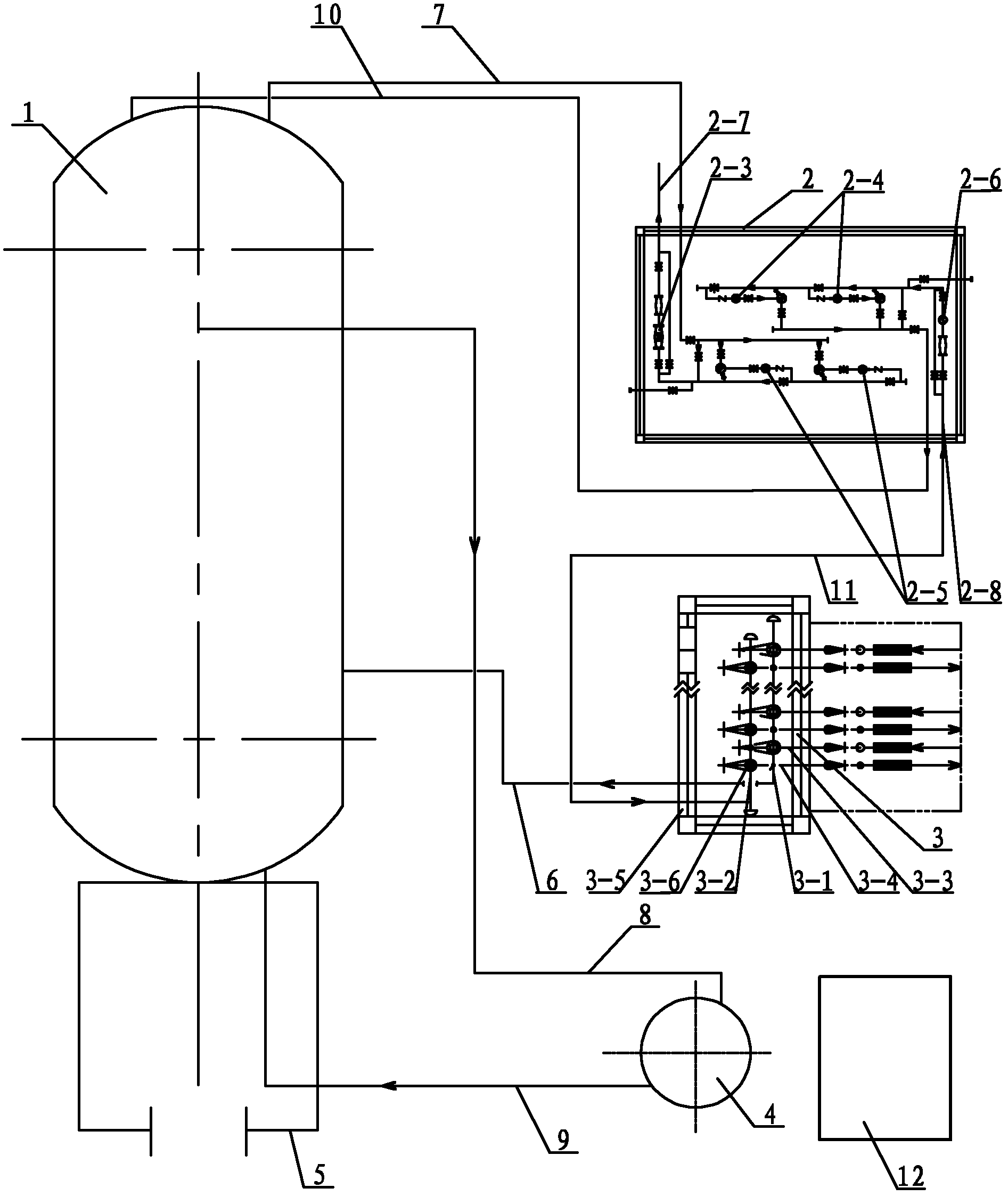
[0008] Specific implementation mode one: combine Figure 1 to Figure 5 Describe this embodiment, this embodiment includes an oil and gas treatment device 1, a numerically controlled oil-water pressurized metering box 2, a numerically controlled oil-collecting and water-distributing valve group box 3, a natural gas dryer 4, a skid-mounted fire room 5, a first pipeline 6, a second The pipeline 7, the third pipeline 8, the fourth pipeline 9, the fifth pipeline 10, the sixth pipeline 11 and the central control room 12, the skid-mounted fire room 5 is set on the fire pipe on the oil and gas treatment device 1 At the entrance 1-11-1, one end of the first pipeline 6 communicates with the liquid inlet 1-1-1 on the oil and gas treatment device 1, and the other end of the first pipeline 6 communicates with the numerical control oil collection and water distribution valve group box 3 The oil collection manifold 3-1 is connected, one end of the second pipeline 7 is connected with the oil ...

specific Embodiment approach 2

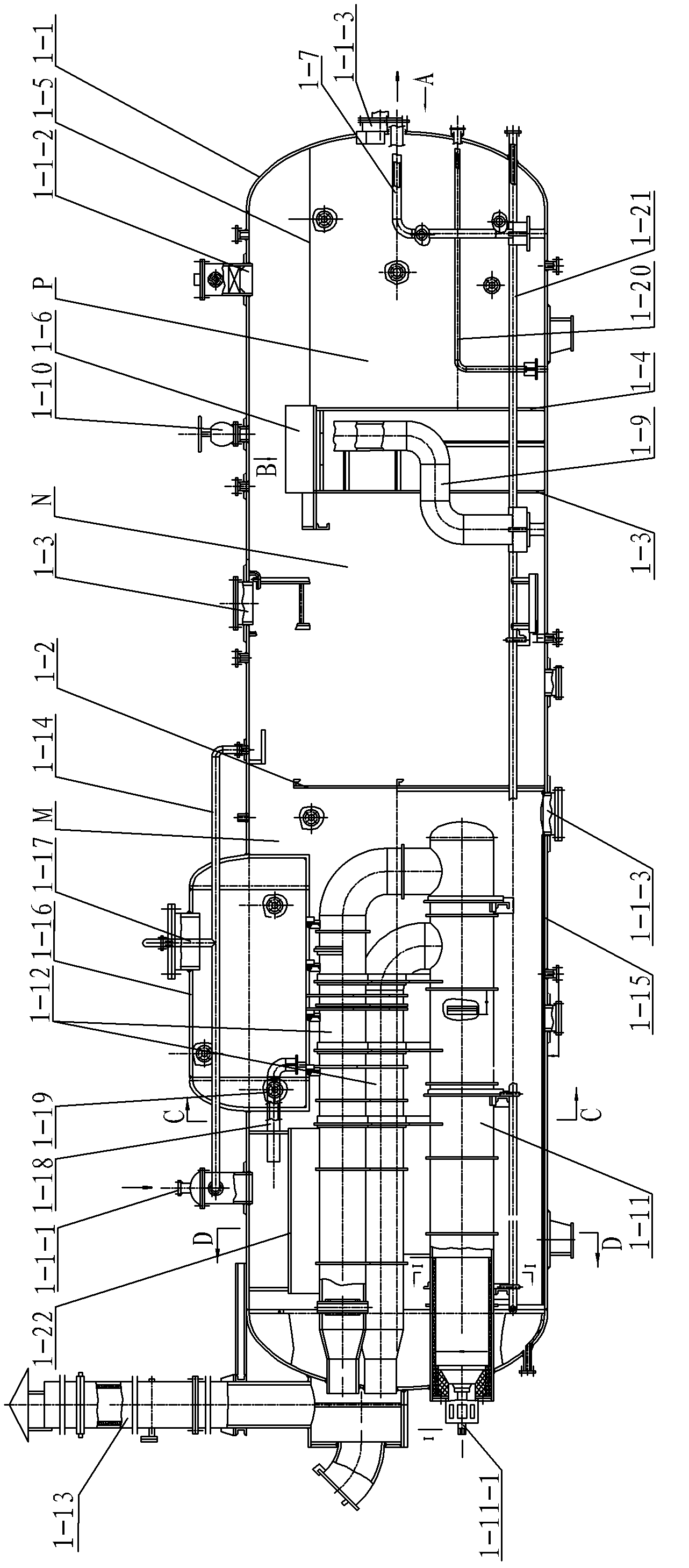
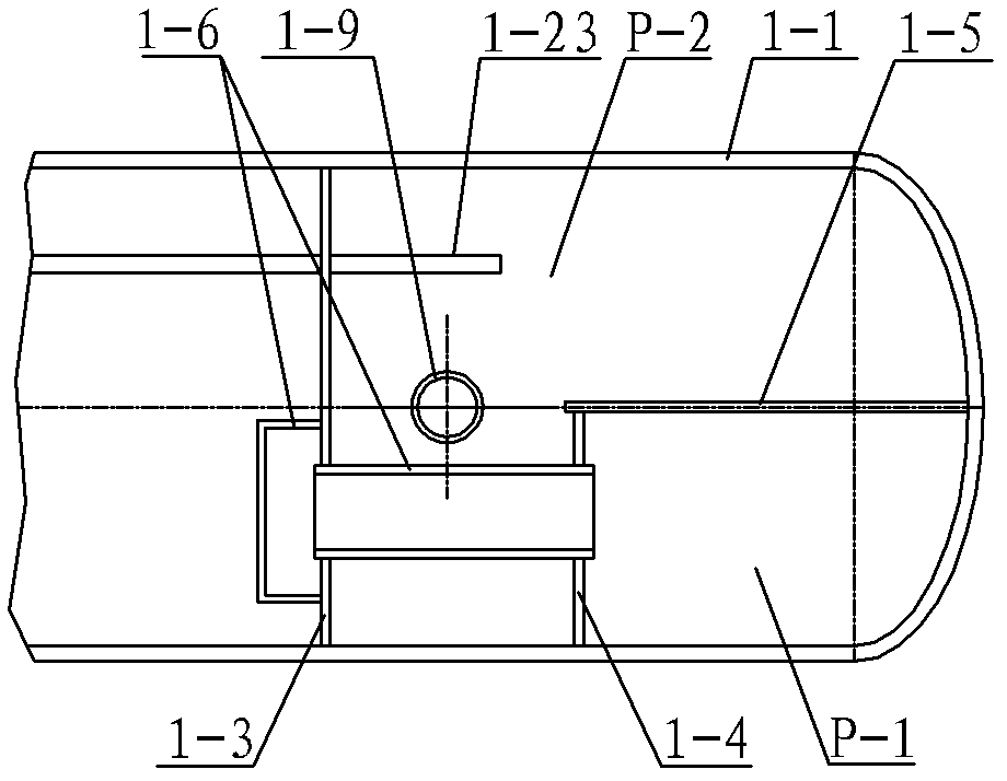
[0009] Specific implementation mode two: combination Figure 2 ~ Figure 4Describe this embodiment, the oil and gas treatment device 1 of this embodiment includes a tank body 1-1, a first partition 1-2, a second partition 1-3, a third partition 1-4, a fourth partition 1- 5. Oil collection tank 1-6, oil outlet pipe 1-7, water outlet pipe 1-8, adjustable weir pipe 1-9, adjustable weir pipe valve 1-10, fire pipe 1-11, smoke pipe 1-12, chimney 1-13, main air balance pipe 1-14, balance water tank 1-16, auxiliary air balance pipe 1-17, water supply pipe 1-18, water supply valve 1-19, buffer weir plate 1-22, water weir pipe 1- 23 and two fuel oil pipes 1-20, the first partition 1-2 and the second partition 1-3 are sequentially arranged in the tank body 1-1 along the cross-sectional direction of the tank body 1-1, the first partition The cavity between the plate 1-2 and the inner wall of the tank body 1-1 is the heating section M, the cavity between the first partition 1-2 and the sec...

specific Embodiment approach 3

[0010] Specific implementation mode three: combination figure 2 with Figure 4 This embodiment is described. The difference between this embodiment and the second embodiment is that it also adds a heating coil 1-21. The heating coil 1-21 is arranged at the bottom of the inner cavity of the tank body 1-1. The heating coil 1-21 The water inlet and outlet of 21 are all arranged outside the tank body 1-1, and the temperature and pressure of the heating coil 1-21 are transmitted to the central control room through data transmission (data transmission methods include cable transmission, wireless network bridge, GPRS) 12 for monitoring. The water outlet of the heating coil 1-21 is connected to the user, and the heat of the heating section M is used to heat the water in the heating coil 1-21, so that the heat of the heating section M is effectively used. Other components and connections are the same as those in the second embodiment.


PUM


Abstract

The invention discloses a digital box type fast-assembling oil-gas gathering and transferring system, which relates to an oil transfer station and is used for solving the problems of a large amount of assorted equipment, complex internal pipe network, large floor area, a large quantity of operating personnel and high running cost existing in the conventional oil transfer station as well as difficulty in controlling the water replenishing amount due to the adoption of manual water replenishment during the running of a four-in-one combined device. An oil-gas treatment device is connected with adigitally-controlled oil collecting water distribution valve bank box through a first pipeline; the oil-gas treatment device is connected with a digitally-controlled oil-water boosting metering box through a second pipeline; the oil-gas treatment device is connected with a natural gas drier through a third pipeline; one end of a fourth pipeline is connected with the natural drier, and the other end of the fourth pipeline is connected with the inlet of a fire pipe; one end of a fifth pipeline is communicated with a water outlet pipe, and the other end of the fifth pipeline is communicated withthe inlet of a water pipe; one end of a sixth pipeline is communicated with the outlet of the water pipe, and the other end of the sixth pipeline is communicated with a water doping header; and the oil gas treatment device, the digitally-controlled oil-water boosting metering box, the digitally-controlled oil collecting water distribution valve bank box and the natural gas drier are monitored through data transmission. The digital box type fast-assembling oil-gas gathering and transferring system is applied to oil-gas gathering and transferring.

Description

technical field [0001] The invention relates to an oil transfer station. Background technique [0002] The traditional oil transfer station mainly realizes the task of crude oil transfer. Crude oil transfer requires a four-in-one combination device, a natural gas dehydration device, an oil-water booster pump room, an oil collection and water distribution valve group, and a duty room. The incoming liquid (mixed liquid) between the valve groups is collected between the oil collection and water distribution valve groups of the oil transfer station. After being separated, settled, heated and buffered by the four-in-one combination device in the station, the separated oil enters the oil-water booster pump room and passes through the external The pump is pressurized and the flow meter is used for external transmission. The separated associated gas is dehydrated by the natural gas dehydration device and then sent to the heating furnace as fuel. The separated water enters the oil-wa...

Claims


Application Information

Patent Timeline
IPC IPC(8): B67D7/04B67D7/06
Inventor 鲍云波
Owner 鲍云波
Why Eureka
Try Eureka