
Resonance demodulation double isolate frequency spectrum method for detecting crack of gear shaft

A technology of resonance demodulation and gear shaft, which is applied in the direction of machine gear/transmission mechanism testing, etc., can solve the problems of high cost, static operation, and limitation, so as to ensure the safety of equipment, avoid production stop loss, and reduce loss.

Active Publication Date: 2012-04-25
TANGZHI SCI & TECH HUNAN DEV CO LTD
View PDF3 Cites 19 Cited by
  • Summary
  • Abstract
  • Description
  • Claims
  • Application Information

AI Technical Summary

Problems solved by technology

The disadvantage of this technology is not only that it must be operated statically, but also that the machine needs to be partially disassembled to expose the test surface (or test point) for operation, especially the cracks or faults close to the inside of the test surface (point) (for example, within 10mm) cannot be found. point
[0009] Since the above-mentioned technologies need to be operated when the machine is stopped or even partially or completely disassembled, it is impossible to use these technologies to detect the machine frequently, because these technologies cannot find small initial cracks, and small cracks may be detected in the next regular It develops to broken shaft before detection. Therefore, this kind of off-line (that is, it cannot be carried out at any time during mechanical operation) detection technology is very limited in preventing accidents, and the cost of using these technologies for detection (outage for production The loss of benefits, the loss of man-hours for mechanical disassembly during inspection, and the additional damage to machinery for disassembly inspection) are high, so it cannot meet the needs of low-cost, low-loss, and frequent inspections of machinery to ensure safety.

Method used


Image

  • Resonance demodulation double isolate frequency spectrum method for detecting crack of gear shaft
  • Resonance demodulation double isolate frequency spectrum method for detecting crack of gear shaft
  • Resonance demodulation double isolate frequency spectrum method for detecting crack of gear shaft

Examples


Embodiment Construction

[0035] Specific embodiments of the present invention will be described in detail below in conjunction with the accompanying drawings.

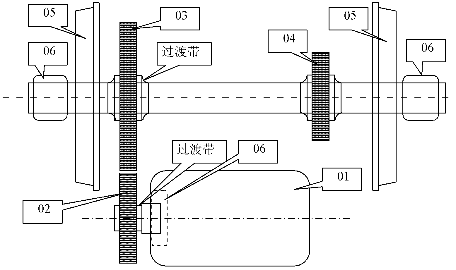
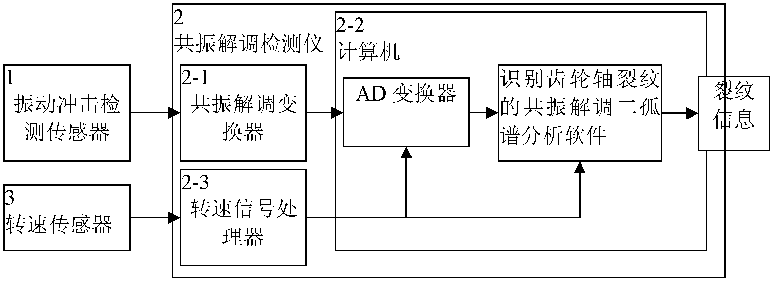
[0036] Gear transmission components include motor (01), gears (02~04), gear shafts, bearings (06~07), vibration shock detection sensor (1) installed on the bearing seat close to the gear, and resonance demodulation detector (2), the rotational speed sensor (3) and the AD converter installed in the computer (2-2) contained in the resonance demodulation detector (2) and the resonance demodulation two-solitary spectrum analysis software for identifying the crack of the gear shaft and in The rotational speed signal processor (2-3) installed in the resonance demodulation detector (2), the rotational speed signal output by the rotational speed sensor (3) is sent to the rotational speed signal processor (2-3) in the resonance demodulation detector (2) ), the output speed signal after processing is sent to the AD converter to control the AD conversion...


PUM


Abstract

The invention discloses a resonance demodulation double isolate frequency spectrum method for detecting crack of a gear shaft. Analysis of resonance demodulation wave is obtained by performing resonance demodulation separation processing and AD (Analog-Digital) converter sampling on a vibration impact signal detected on a bearing close to a gear; and if discovering that the resonance demodulationtime domain waveform occurs two clusters of basically symmetric meshing impact waves in each rotation period of a shaft where the gear is positioned, a meshing impact spectrum of the gear occurs in an FFT (Fast Fourier Transform) analytical spectrum of the resonance deformation time domain waveform and double isolate frequency spectrum equal to rotation speed frequency of the gear shaft occurs, it is reported that the shaft has the crack. The method provided by the invention has the advantages of low cost, low loss and capability of on-line frequent detection, and plays an important role in guaranteeing safety of equipment, particularly personal safety.

Description

technical field [0001] The invention relates to the technical field of signal detection, analysis and diagnosis of equipment fault diagnosis, in particular to a resonance demodulation two-solitary spectrum method for detecting cracks of gear shafts. Background technique [0002] Whether it is a gear shaft system that is integrally processed with the gear or a gear shaft system that installs the gear on the shaft through interference fit, it is due to the fact that when they transmit torque, the equivalent shaft diameter, equivalent cross-sectional area, and equivalent rigidity of different parts Different, but stress concentration and alternating fatigue occur at the transition parts where the shaft diameter, cross-sectional area, and stiffness change, and then cracks and fractures occur, causing major accidents in mechanical equipment, such as the axles of some high-speed trains in the transition zone between gears and axles. Cracks appear. figure 1 Shown is the structural...

Claims


Application Information

Patent Timeline
IPC IPC(8): G01M13/02
Inventor 唐德尧黄贵发曾承志王智
Owner TANGZHI SCI & TECH HUNAN DEV CO LTD
Learn More