Method of laser-welding and method of manufacturig battery including the same

A technology of laser welding and manufacturing method, applied in secondary battery manufacturing, laser welding equipment, small-sized batteries/batteries, etc., can solve the problems of uneven surface state, difficulty in roughening, unstable heat input of laser welding, etc. , to achieve the effect of uniform welding

Active Publication Date: 2012-04-25
TOYOTA JIDOSHA KK
View PDF1 Cites 26 Cited by
  • Summary
  • Abstract
  • Description
  • Claims
  • Application Information

AI Technical Summary

Problems solved by technology

[0011] However, in the roughening method described in Patent Document 1, the roughening accuracy is good compared to most, but it tends to have steps, uneven surfaces, etc. Uniform roughening of small parts is difficult, and unevenness in the surface state is likely to occur
In addition, in the above-mentioned roughening method, a mask during rough processing and cleaning after processing are required, and there is a problem that the process becomes complicated, and it is difficult to use it in a mass production process.
[0012] In particular, when a high-output laser is used for welding, it is easily affected by unevenness in the surface state of the welded part, product state (such as shape, assembly accuracy), etc., so the heat input during laser welding becomes unstable, and it is easy to produce welding defects
[0013]As mentioned above, in the conventional laser welding method, it is difficult to achieve uniform welding of components with high laser reflectivity on the surface

Method used


Image

  • Method of laser-welding and method of manufacturig battery including the same
  • Method of laser-welding and method of manufacturig battery including the same
  • Method of laser-welding and method of manufacturig battery including the same

Examples


Embodiment Construction

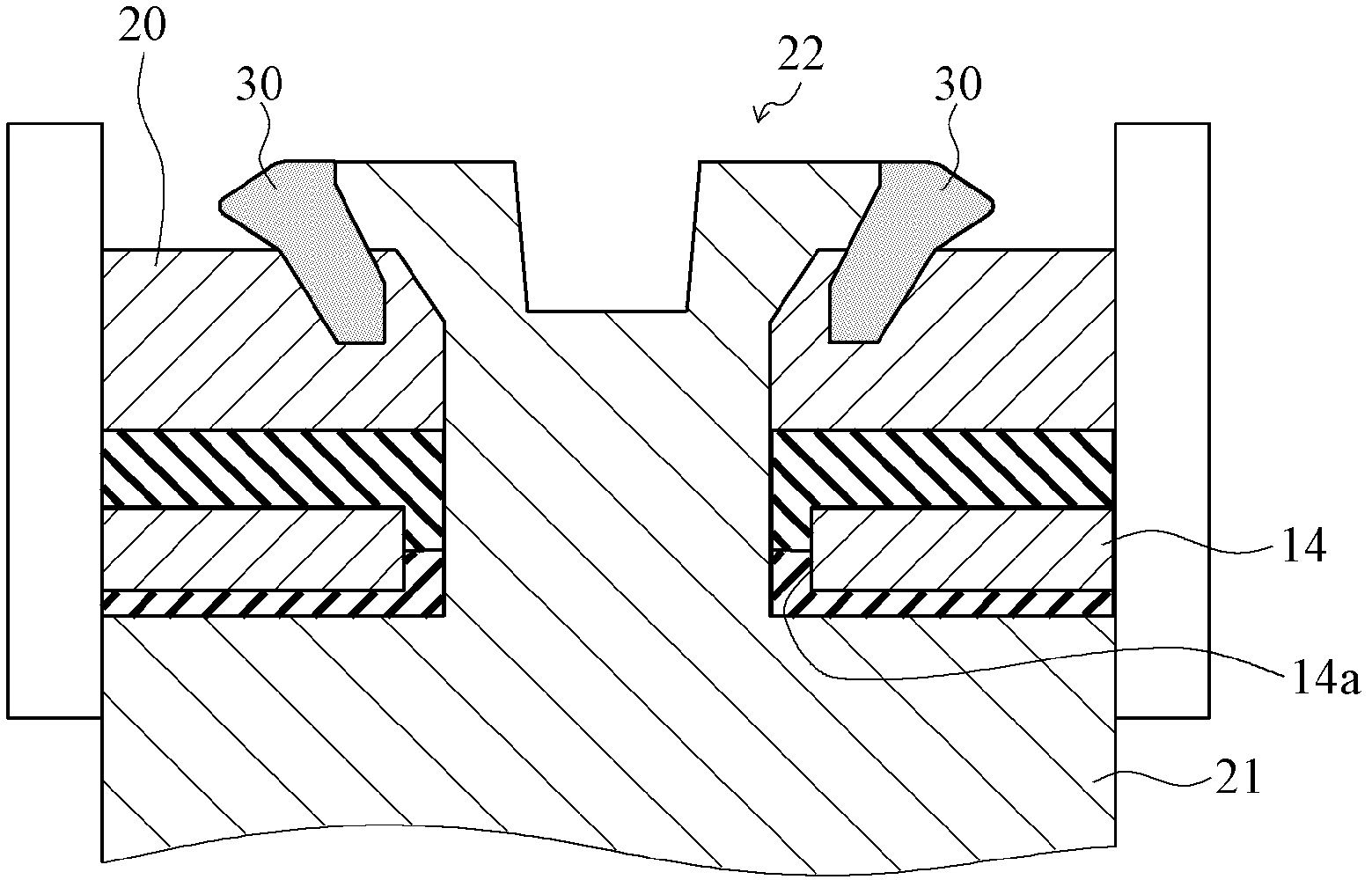
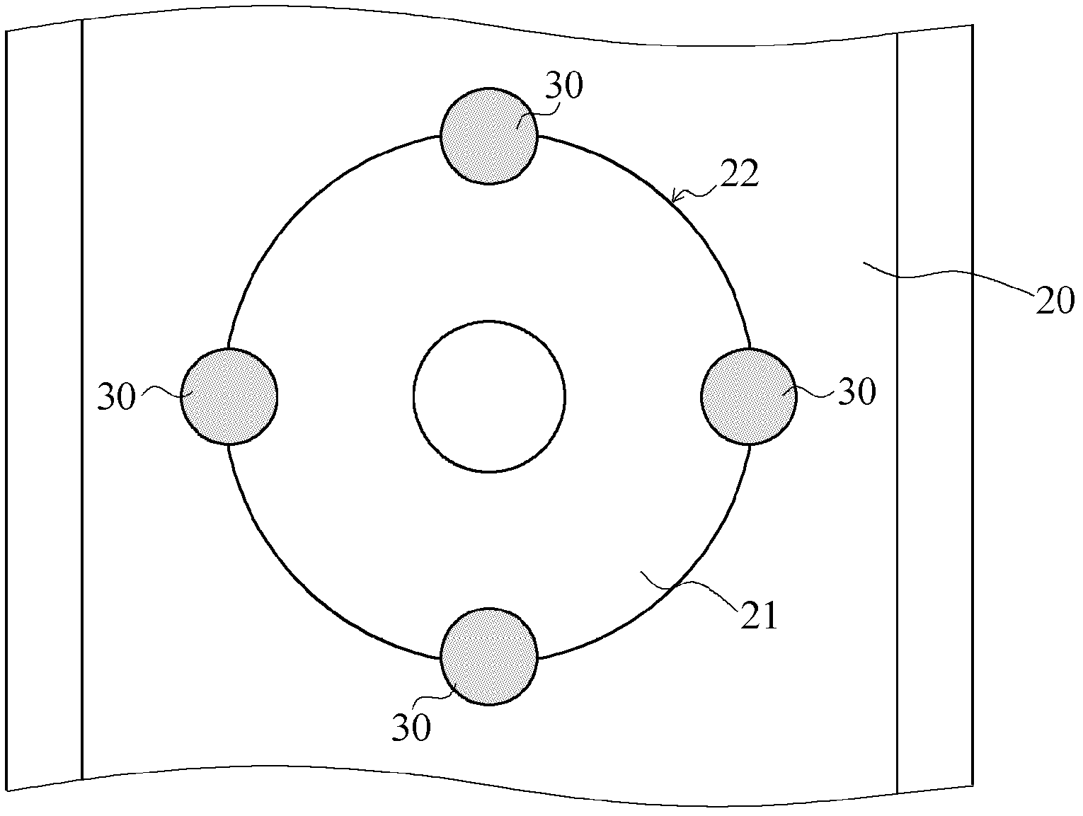
[0038] Next, laser welding step S1 as one embodiment of the laser welding method according to the present invention will be described with reference to the drawings. In the laser welding step S1 , the negative electrode terminal 20 constituting the negative electrode of the battery 10 and the negative electrode lead 21 are laser welded.

[0039] Next, the schematic structure of the battery 10 to be welded in the laser welding step S1 will be described.

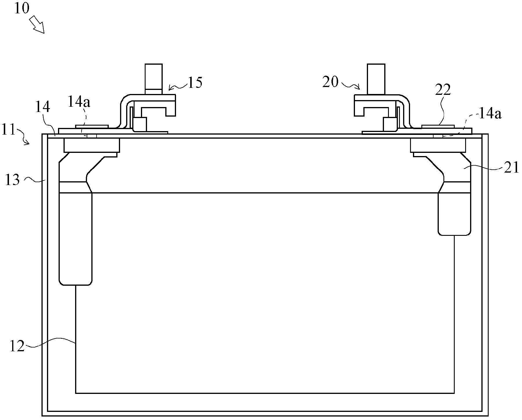
[0040] The battery 10 is a lithium-ion secondary battery, such as figure 1 As shown, a power generating element 12 is accommodated inside the casing 11 . The casing 11 has a container portion 13 constituted by a box, and a lid portion 14 that closes an opening surface of the container portion 13 . The cover part 14 has two openings 14a, 14a, and the positive electrode terminal 15 and the negative electrode terminal 20 respectively protrude outward from these openings 14a, 14a.

[0041] The negative terminal 20 is an externa...


PUM


Abstract

Provided is a method of laser-welding that can achieve uniform welding of a member with large laser reflectance on a surface thereof. A laser welding step (S1) includes a surface roughening step (S11) in which a first laser processing device irradiates laser light to a surface (each welding portion (31)) of a welding section (30, 30, 30, 30) between a negative electrode terminal (20) (a first member) and a negative electrode lead (21) (a second member) and carries out roughening, thereby forming a laser marker (32) on the surface; and a welding step (S12) in which a second laser processing device irradiates laser light to each welding portion (31) roughened in the surface roughening step (S11) and melts each welding portion (31), thereby carrying out the laser-welding of the negative electrode terminal (20) to the negative electrode lead (21).

Description

technical field [0001] The present invention relates to a laser welding method and a battery manufacturing method including the laser welding method, and particularly relates to a laser welding technique for components such as copper components with high laser reflectivity on the surface. Background technique [0002] Conventionally, the technique of joining two metal members by laser welding has been widely used in the manufacturing field. [0003] In particular, laser welding using a YAG laser can also be used in an atmospheric atmosphere, so compared with other welding techniques such as electron beam welding (EBW) performed in a vacuum atmosphere, it is very advantageous in terms of equipment cost and control, and has Tendency to be actively introduced in mass production processes. [0004] However, in the laser welding of metal components (copper components, etc.) with high laser reflectivity on the surface, the laser beam is reflected on the surface of the component a...

Claims


Application Information

Patent Timeline
Patent Type & Authority Applications(China)
IPC IPC(8): B23K26/20B23K26/14B23K26/21H01M50/528H01M50/536H01M50/55H01M50/553H01M50/562H01M50/566
CPCH01M2/30Y02E60/12B23K26/32B23K26/421B23K33/00B23K26/123B23K26/0078H01M10/0525H01M2/26B21K25/00B23K26/28B23K26/60B23K26/3584Y02E60/10Y02P70/50H01M50/553H01M50/55H01M50/566H01M50/536H01M50/562B23K26/21B23K26/12H01M10/04B23K2101/38
Inventor 三宅秀明大岛贵博
Owner TOYOTA JIDOSHA KK
Why Eureka
Try Eureka