Retroreflective sheeting including a low index coating
A low-refractive-index layer and low-refractive-index technology, applied in layered products, optics, instruments, etc., can solve problems such as insufficient durability and insufficient whiteness of metal coatings
- Summary
- Abstract
- Description
- Claims
- Application Information
AI Technical Summary
Problems solved by technology
Method used
Image

Examples
example 1
[0095] Coating Solutions 1-9 were prepared using the hydrophobic resins listed in Table 1. For each coating solution, resin and fumed silica (available as TS-530 from Cabot Corporation, Billerica MA) having the weight ratios specified in Table I were mixed with the corresponding solvent also specified in Table I. The weight part of the resin is 1. For example, for coating solution 1, the weight ratio of resin FC2145 to fumed silica is 1:5.
[0096] The resin used in Coating Solutions 1, 2, and 9 was Dyneon Fluoroelastomer Copolymer FC2145 (available from Dyneon LLC, Oakdale MN). The resin used in coating solutions 3 and 4 was SPU-5k, which is a silicone polyurea formed from the reaction between αω aminopropyl polydimethylsiloxane and m-tetramethylxylene diisocyanate, As generally described in Example #23 of US Patent No. 6,355,759. The resin used in coating solutions 5 and 6 was SR-351, a UV-polymerizable monomer (available from Sartomer Company, Exton PA). The resin used ...
example 2
[0103] Coating solutions 10-15 were prepared using hydrophilic polyvinyl alcohol as specified in Table II (available as Poval PVA-235 from Kuraray America, Houston TX). For each coating solution, resin and fumed silica (available as Cabo-O-Sperse PG002 from Cabot Corporation, Billerica MA) were mixed in the weight ratios specified in Table II. The weight part of resin is 1. For example, for coating solution 10, the weight ratio of resin PVA-235 to fumed silica was 1:4. First, PVA-235 resin was added as a 7% by weight solution in water into a stainless steel beaker fitted with an air mixer operated at low speed to minimize foaming. Tergitol Min-Foam XL (available from Dow Chemical Company, Midland MI) at 1% by weight of PVA-235 and 2-3% by weight of NH 4 OH was added to the mixer to adjust the pH to about 9.5-10. Fumed silica was then added as a 20% by weight solution in water. If necessary, a sufficient amount of CX-100 as specified in Table II by weight percent of the res...
example 3
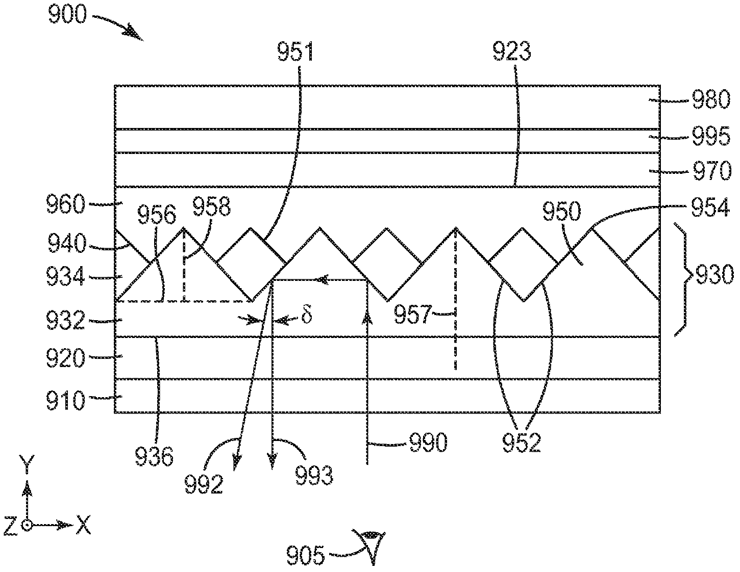
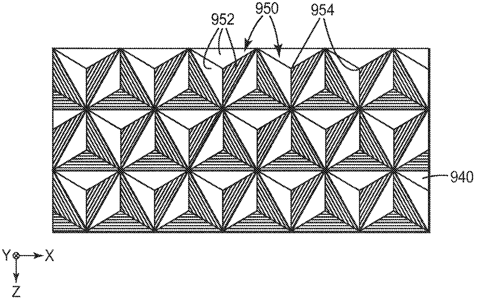
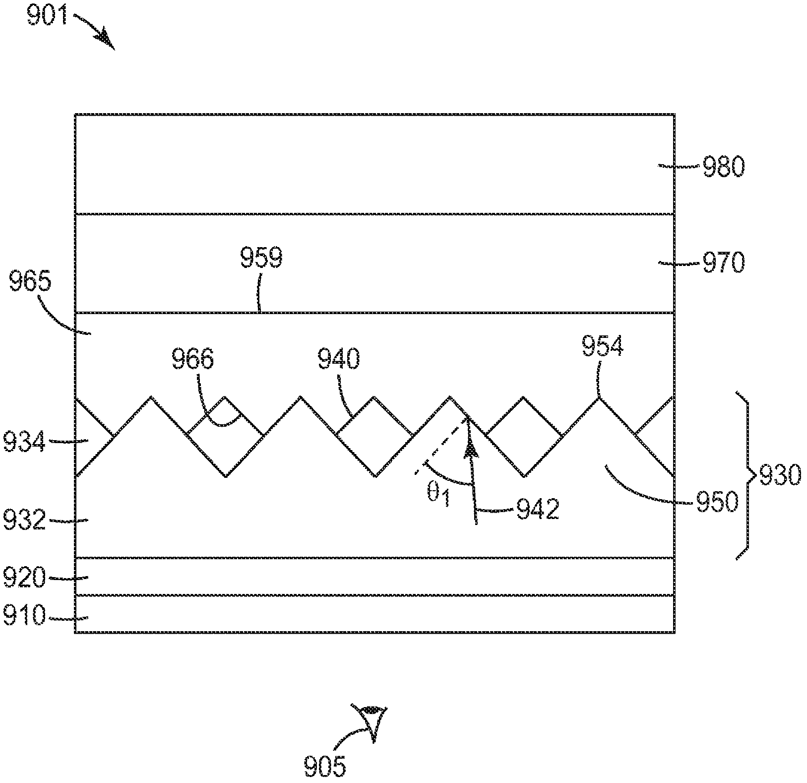
[0108] A retroreflecting optical construction 3000 was prepared, a schematic side view of which is shown in Image 6 . Optical Construct 3000 similar to Figure 1A The corresponding configuration in , and includes a flexible prismatic retroreflective layer 930 and a low refractive index layer 960 coated on the retroreflective layer. The low index layer substantially planarizes the structured side of the retroreflective layer. Figure 7A with 7B Schematic top and side views, respectively, of a single prism in a prismatic retroreflective layer. Figure 7A with 7B Angles are measured in degrees and dimensions are measured in mils. Each face of the prisms in the retroreflective layer is a right triangle and the base is an isosceles triangle. Prisms were prepared using methods generally described in, for example, US Patent Nos. 6,843,571 and 5,691,846, the disclosures of which are incorporated herein by reference in their entirety.
[0109] Retroreflecting optical constructio...
PUM
| Property | Measurement | Unit |
|---|---|---|
| Diameter | aaaaa | aaaaa |
Abstract
Description
Claims
Application Information
 - R&D
- Intellectual Property
- Life Sciences
- Materials
- Tech Scout
- Unparalleled Data Quality
- Higher Quality Content
- 60% Fewer Hallucinations
Browse by: Latest US Patents, China's latest patents, Technical Efficacy Thesaurus, Application Domain, Technology Topic, Popular Technical Reports.
© 2025 PatSnap. All rights reserved.Legal|Privacy policy|Modern Slavery Act Transparency Statement|Sitemap|About US| Contact US: help@patsnap.com