Organic electroluminescent element
An electroluminescence element and luminescence technology, which is applied in the direction of electroluminescence light sources, electrical components, organic semiconductor devices, etc., can solve the problems of short life of blue phosphorescence, short life, insufficient luminous efficiency, etc.
- Summary
- Abstract
- Description
- Claims
- Application Information
AI Technical Summary
Problems solved by technology
Method used
Image
Examples
no. 1 Embodiment approach
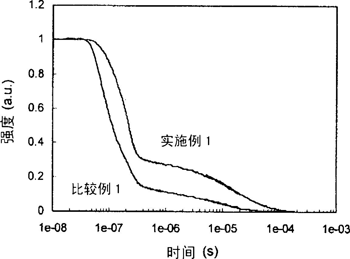
[0061] The present invention utilizes the TTF phenomenon. First, the following explains the TTF phenomenon.
[0062] Holes and electrons injected from the anode and cathode are recombined in the light-emitting layer to generate excitons. As known in the past, the rotation state is 25% singlet excitons and 75% triplet excitons. In the previously known fluorescent element, 25% of singlet excitons emit light when they relax to the ground state, but the remaining 75% of triplet excitons do not emit light but return to the ground state through a thermal inactivation process. Therefore, the theoretical limit value of the internal quantum efficiency of the conventional fluorescent element can be said to be 25%.
[0063] On the other hand, the behavior of triplet excitons generated inside organic matter has been theoretically studied. According to S.M.Bachilo et al. (J.Phys.Cem.A, 104, 7711 (2000)), if it is assumed that the quintet and other high-order excitons immediately return to th...
no. 2 Embodiment approach
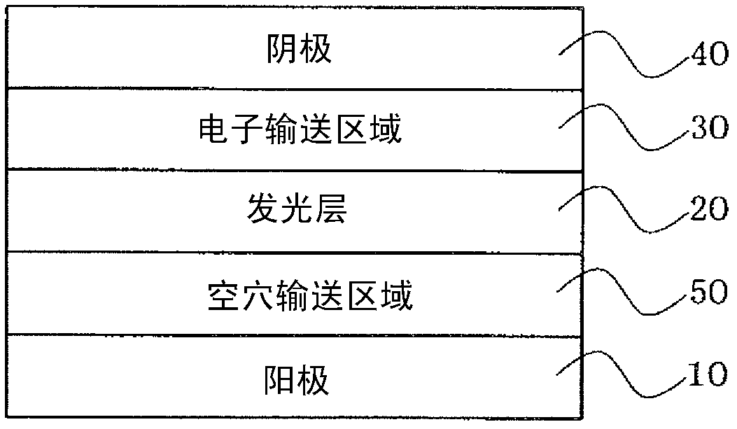
[0224] The device of the present invention may have a tandem device structure having at least two organic layer units including a light-emitting layer. An intermediate layer (also referred to as an intermediate conductive layer, an electrochemical generating layer, or CGL) exists between the two light-emitting layers. Each unit can be equipped with an electron transport area. At least one light-emitting layer is a fluorescent light-emitting layer, and the unit containing the light-emitting layer satisfies the aforementioned requirements. An example of a specific stacking order is shown below. In addition, the light-emitting layer described below may be a laminate of a plurality of light-emitting layers, or may be one organic layer unit including the charge blocking layer of the third embodiment described later.
[0225] Anode / fluorescent light-emitting layer / intermediate layer / fluorescent light-emitting layer / barrier layer / cathode
[0226] Anode / fluorescent light-emitting layer / ...
no. 3 Embodiment approach
[0234] In this embodiment, an anode, a plurality of light-emitting layers, an electron transport region, and a cathode are sequentially provided. A charge blocking layer is provided between any two light-emitting layers among the plurality of light-emitting layers. The light-emitting layer close to the charge blocking layer is fluorescent The light-emitting layer satisfies the above requirements.
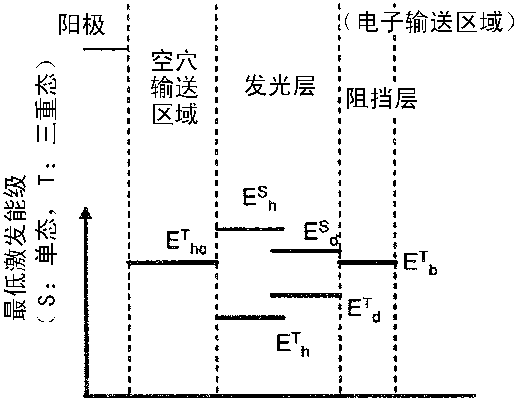
[0235] As the structure of a suitable organic EL element according to the present embodiment, as described in Japanese Patent No. 4134280, U.S. Patent Publication US2007 / 0273270A1, and International Publication WO2008 / 023623A1, anodes, In the structure of the first light-emitting layer, the charge blocking layer, the second light-emitting layer, and the cathode, there is an electron transport region between the second light-emitting layer and the cathode, and the electron transport region has a structure for preventing the diffusion of triplet excitons. Barrier layer. Here, the charge...
PUM
 Abstract
Description
Claims
Application Information
 - R&D
- Intellectual Property
- Life Sciences
- Materials
- Tech Scout
- Unparalleled Data Quality
- Higher Quality Content
- 60% Fewer Hallucinations
Browse by: Latest US Patents, China's latest patents, Technical Efficacy Thesaurus, Application Domain, Technology Topic, Popular Technical Reports.
© 2025 PatSnap. All rights reserved.Legal|Privacy policy|Modern Slavery Act Transparency Statement|Sitemap|About US| Contact US: help@patsnap.com


