Pre-selecting and tailings discarding process of lean magnetite ores

A lean magnetite and process technology, which is applied in the field of lean magnetite pre-selection and tailing process, can solve the problems of affecting the effect of pre-selection and throwing tailings, insufficient monomer dissociation degree, waste of grinding energy consumption, etc., so as to reduce grinding Amount and follow-up work load, reduce excessive loss of iron metal, reduce the effect of grinding energy consumption

Inactive Publication Date: 2012-05-02
ANHUI UNIV OF SCI & TECH
View PDF3 Cites 36 Cited by
  • Summary
  • Abstract
  • Description
  • Claims
  • Application Information

AI Technical Summary

Problems solved by technology

The current process mostly adopts coarse grinding separation or medium crushing separation to realize the pre-selection and throwing of ultra-lean magnetite. However, the coarse grinding separation method has high cost and low efficiency due to the high energy consumption and high steel consumption of grinding. The ratio is low, and the medi

Method used


Image

  • Pre-selecting and tailings discarding process of lean magnetite ores
  • Pre-selecting and tailings discarding process of lean magnetite ores
  • Pre-selecting and tailings discarding process of lean magnetite ores

Examples


Embodiment 1

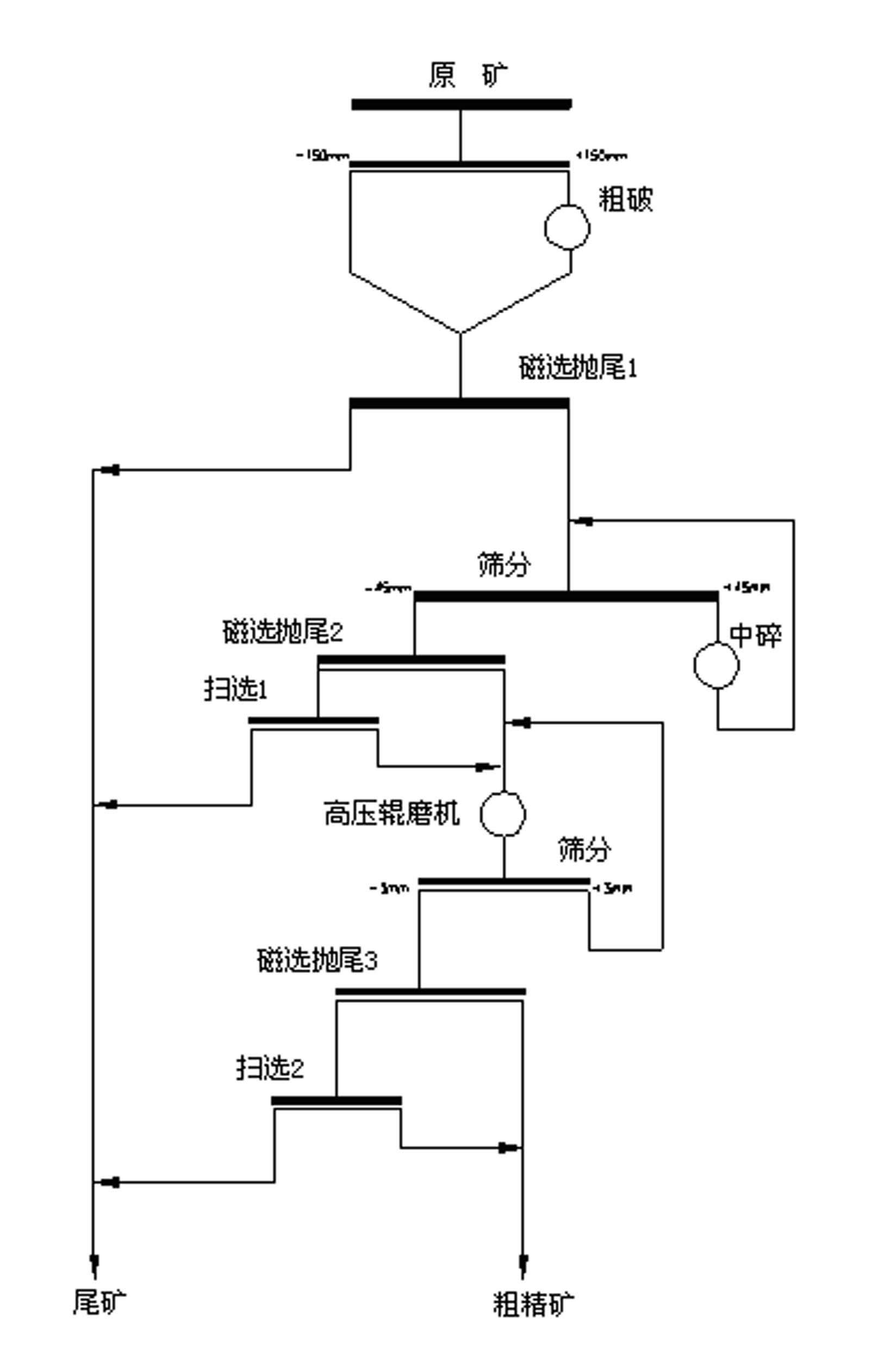
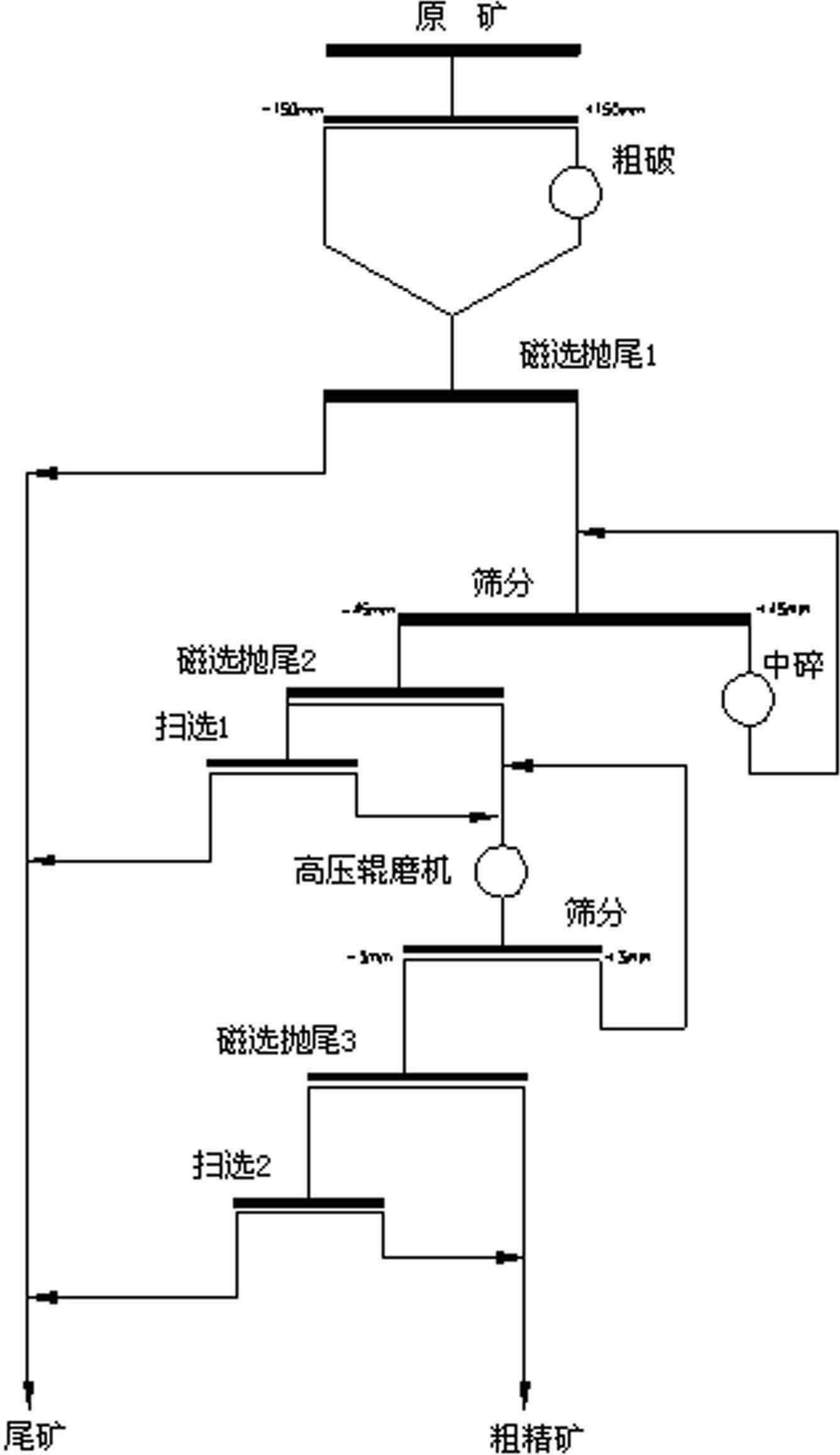
[0028] Such as figure 1 As shown, a. The raw ore is pre-selected and screened, the screen size is 100~200mm, the product on the screen is coarsely crushed and mixed with the product under the screen, and then it is pre-magnetically separated by a magnetic pulley or a dry permanent magnetic separator for large ore Tail throwing operation, throwing away the surrounding rock mixed in mining and part of the dissociated gangue;

[0029] b. The magnetic material after being thrown by the magnetic pulley is screened through a double-layer sieve, the mesh size of the upper layer is 40~50mm, and the mesh size of the bottom layer is 15~20mm; the products on and under the bottom layer are subjected to dry permanent magnetization Magnetic separation tailing operation, and sweeping operation on tailings, the magnetic products obtained by sweeping are mixed into the magnetic products of tailing operation; after the products on the screen are crushed, return to the double-layer screen for i...

Embodiment 2

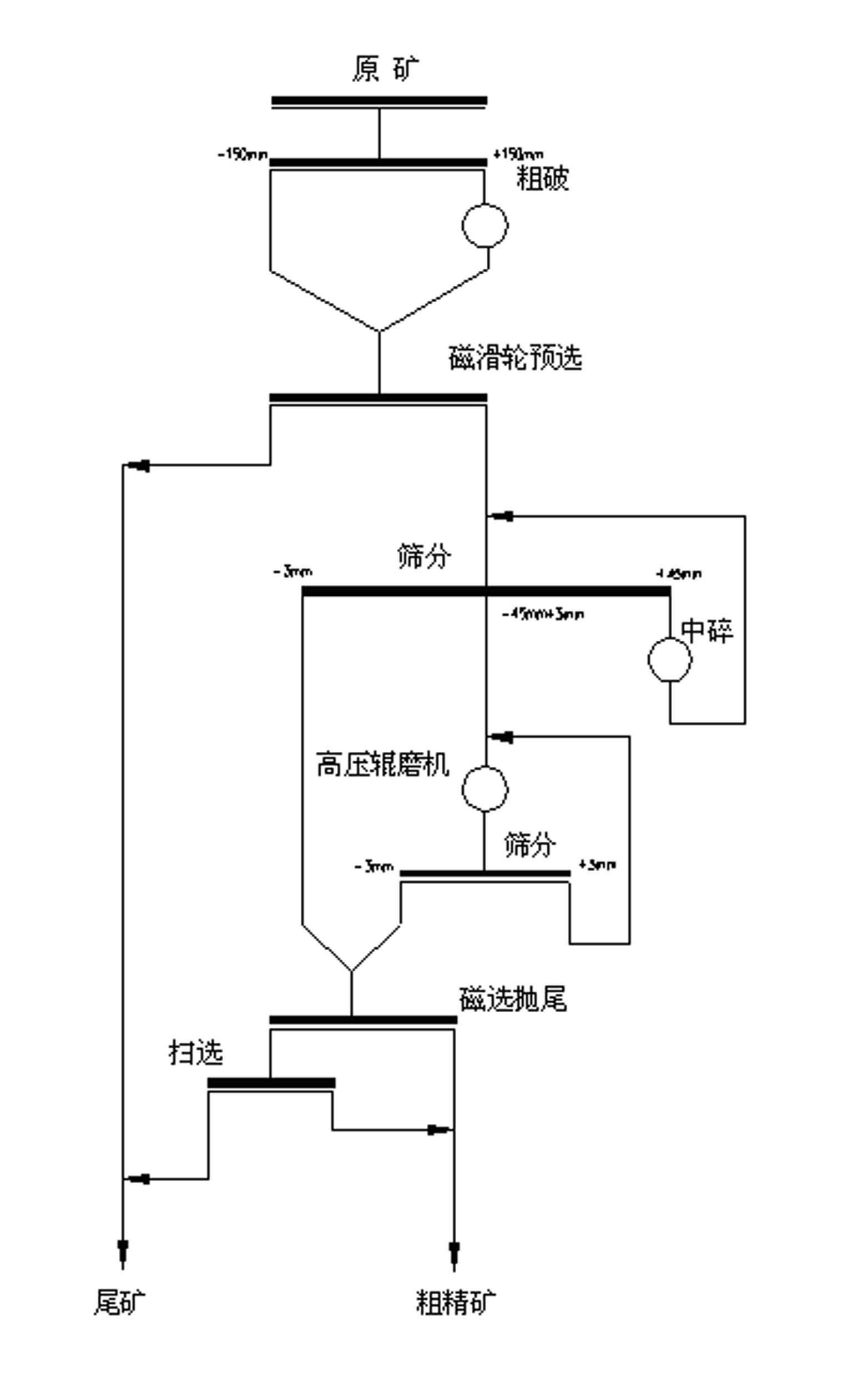
[0034] Such as figure 2 As shown, the difference between this embodiment and Example 1 is that the double-layer sieve in step b selects the sieve size of the upper sieve to be 40-50mm, and the sieve size of the bottom sieve is the same as that of the high-pressure roller mill. The size is the same (3~5mm), the bottom sieve is directly fed into the CTB1021 wet permanent magnet magnetic separator or CG3 up-suction dry permanent magnetic separator for tailing operation, and the bottom sieve is transported to The high-pressure roller mill is ultra-finely crushed, and the material on the upper sieve is crushed and then returned to the double-layer sieve.


PUM

PropertyMeasurementUnit
Magnetic field strengthaaaaaaaaaa

Abstract

The invention discloses a pre-selecting and tailings discarding process of lean magnetite ores, comprising three stages: a coarse crushing stage, an intermediate crushing stage and an ultra-fine crushing stage, wherein fine crushing operation stage can be increased before the ultra-fine crushing stage and after the intermediate crushing stage. The staged magnetic pre-separation and tailings discarding work can be executed by different types of magnetic separators according to the difference of granularity of each crushing stage. Surrounding rocks and partial dissociatve gangue which drop in the tailings are removed in the first discarding work; waste stones which are not removed in the first tailings discarding work and the gangue which is further dissociated after the intermediate crushing stage are removed in the secondary tailings discarding work; and the third tailings discarding work is to discard the tailings after the tailings are ultra-finely crushed by a high-pressure roller mill. After the lean magnetite ores in which the fine particles are embedded are ultra-finely crushed by the high-pressure roller mill, the dissociation degree is further improved, and the magnetic separating and tailings discarding effects are good. The tailings discarding work is designed to reduce the loss of ferrous metal. The complete process can effectively improve the grade of grinding ferrous, can ensure the TFe recovery rate of the work, can improve the grinding characteristics of the material in the grinder, can reduce the quantity of the ore to be grinded, and can reduce the energy consumption of grinding the ores and the cost of separating the ores.

Description

technical field [0001] The invention belongs to the technical field of magnetite beneficiation, and in particular relates to a pre-selection and tailing-throwing process of lean magnetite. Background technique [0002] With the rapid development of my country's iron and steel industry, the demand for iron ore by iron and steel enterprises is increasing day by day, and the characteristics of my country's iron ore resources are that there are many small and medium mines and few large mines; there are many lean ores and few rich ores. The ore is lean iron ore with an iron grade below 30% Fe. There are many associated ores, difficulty in mining and selection, high production cost, lack of market competitiveness, production cannot meet market demand, and the gap between supply and demand continues to expand. Serious dependence. In 2009, my country's iron ore imports increased to 627 million tons. Accompanied by the substantial increase in import volume, the price of iron ore has...

Claims


Application Information

Patent Timeline
IPC IPC(8): B03C1/02B02C23/08
Inventor 焦红光刘松田中良吴金保王怀江朱金波张明旭闵凡飞王超
Owner ANHUI UNIV OF SCI & TECH
Why Eureka
Try Eureka