

Antirust process for connecting rod of automotive engine
A technology for automobile engines and connecting rods, which is applied to connecting rods, mechanical equipment, and devices for coating liquid on the surface, etc. It can solve problems such as difficult automatic production and processing, affecting beats, wasting cleaning liquid and antirust liquid, etc., and meets the requirements of Automated process requirements, reduced labor costs, good anti-rust effect
- Summary
- Abstract
- Description
- Claims
- Application Information
AI Technical Summary
Problems solved by technology
Method used
Image

Examples
Embodiment Construction
[0019] Specific embodiments of the present invention will be described in detail below in conjunction with the accompanying drawings.
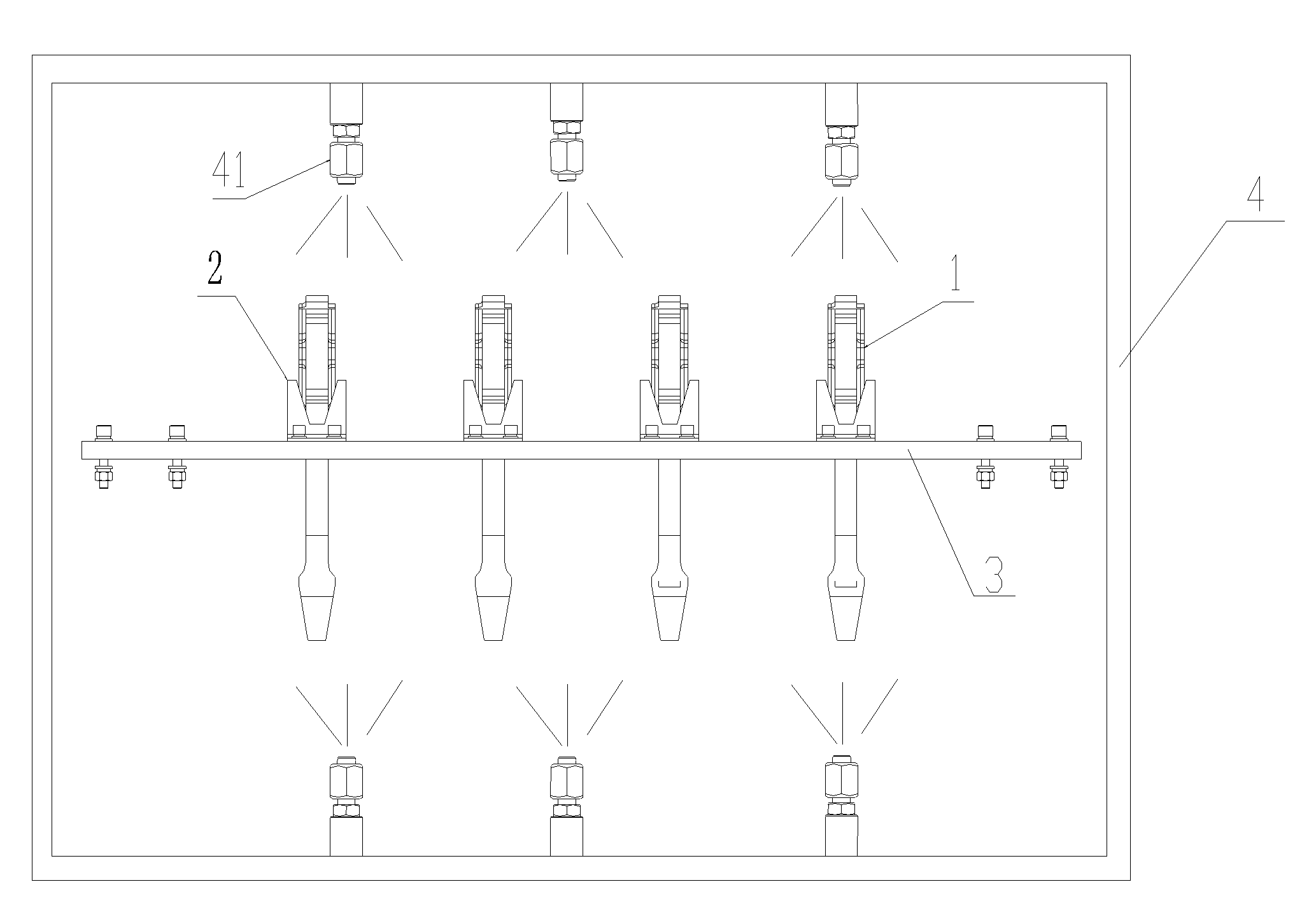
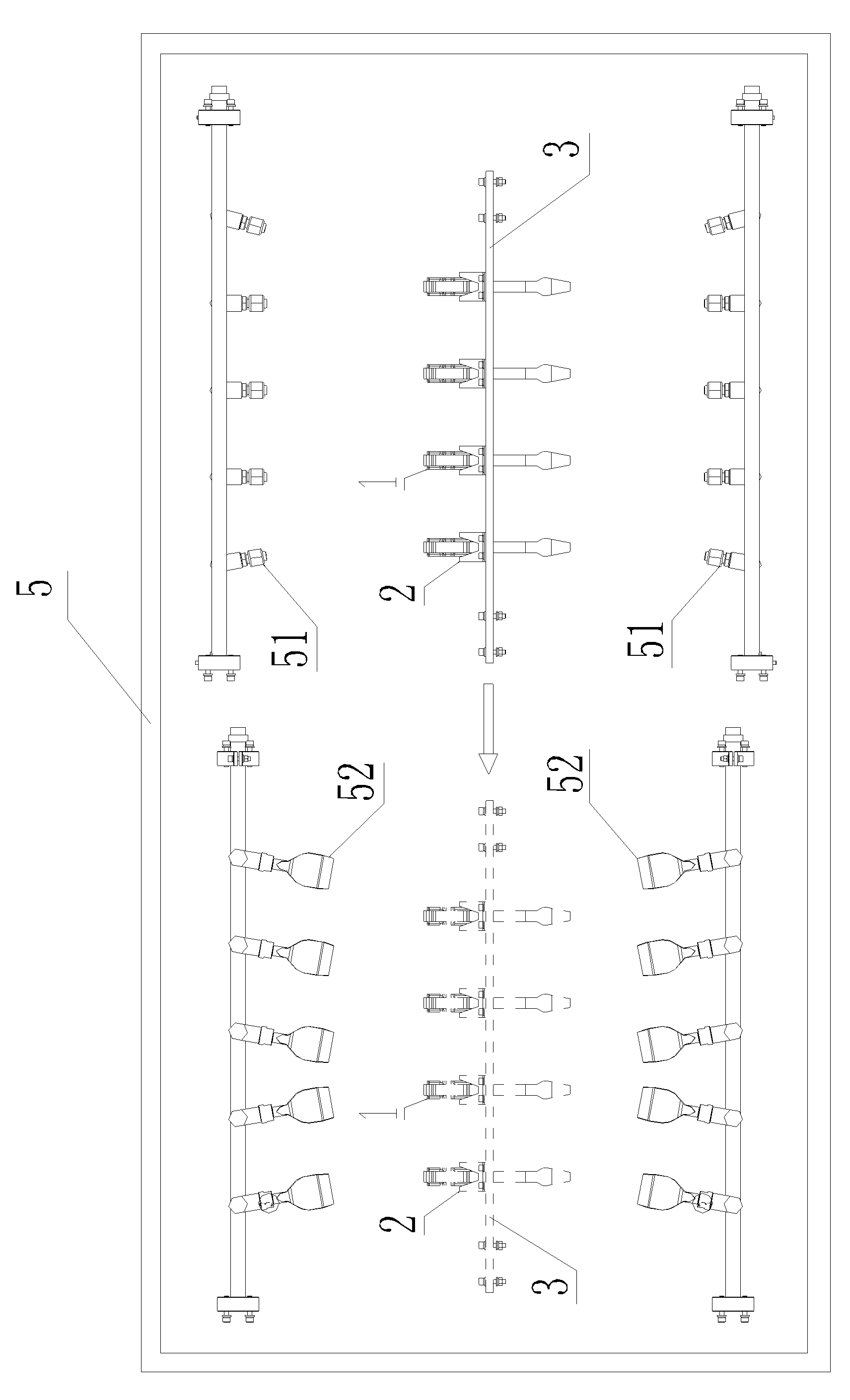
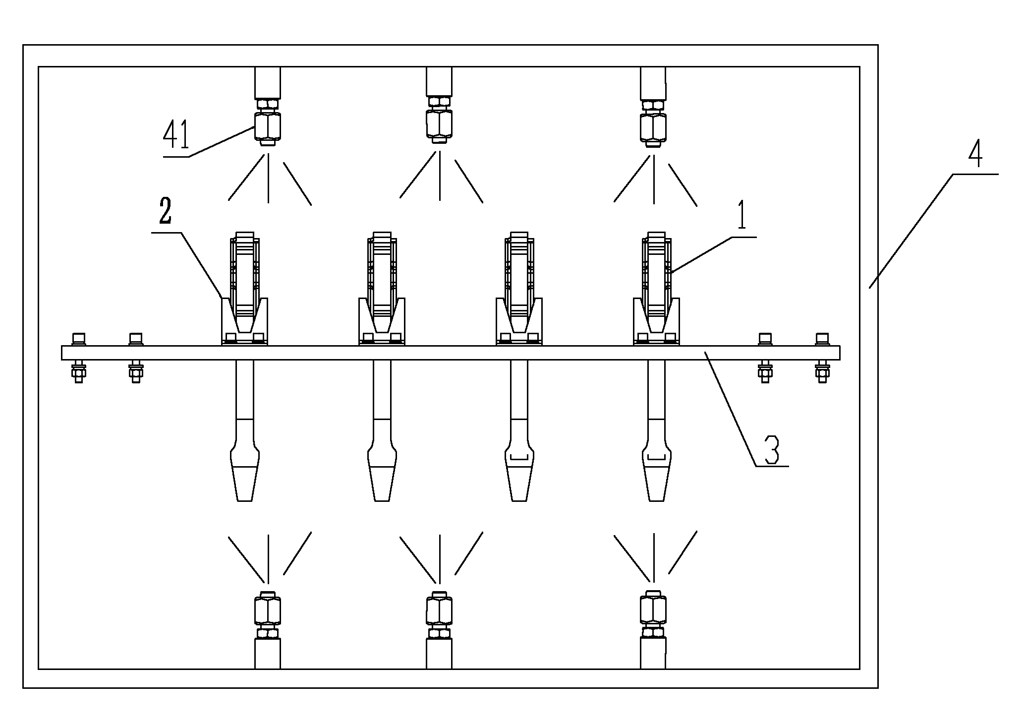
[0020] see figure 1 , figure 2 , the present invention, promptly a kind of antirust technology that is used for automobile engine connecting rod, it comprises the following steps:
[0021] In the preparatory step, four connecting rods 1 with the same weight are supported by the V-shaped groove support structure 2, placed side by side and vertically into a feeder 3, and the connecting rods enter the cleaning room 4, the rinsing room, the drying room through the feeder 3 in sequence. Drying room and spraying room 5;
[0022] In the cleaning step, the connecting rod 1 is cleaned in the cleaning room 4, and the oil and iron filings on the surface of the connecting rod 1 are removed by using the shower nozzles 41 distributed around the connecting rod 1;
[0023] In the rinsing step, the connecting rod 1 is rinsed in the rinsing room, and the co...
PUM
 Abstract
Description
Claims
Application Information