Coal cutter and rocker arm transmission system thereof

A technology of rocker arm drive and shearer, applied in the direction of transmission device, gear transmission device, cutting machine, etc., can solve the problems of small transmission, unfavorable health and safety of operators, large linear speed of the drum, etc., and can reduce the rotation speed. and line speed, improve the working face environment, reduce the effect of structure size

Inactive Publication Date: 2012-05-02
SANY HEAVY EQUIP
View PDF6 Cites 13 Cited by
  • Summary
  • Abstract
  • Description
  • Claims
  • Application Information

AI Technical Summary

Problems solved by technology

[0003] One is the non-planetary reduction transmission system, which adopts three-stage spur gear reduction, but in this scheme, due to the limited reduction ratio of the spur gear and the limited overall structure of the rocker arm, the transmission ratio of the entire rocker arm transmission system is small (usually between 10 and 12 or so), the output speed of the cutting drum is too high. When cutting the coal wall, the coal dust on the working face is too large, which seriously affects the working environment of the working face and is extremely harmful to the health and safety of the workers
[0004] The other is a transmission system with a planetary reduction. Due to the addition of a planetary reducer at the end of the transmission, the transmission ratio has been greatly improved after two-stage spur gears and one-stage planetary transmission deceleration (usually up to 20 to 25), but in this scheme, since the planetary reducer is placed at the output end, in order to meet the strength requirements of the planetary drive, the diameter of the planetary reducer cannot be too small, which will result in the diameter of the hub of the matching cutting drum Larger, under the same diameter, the blades of the cutting drum will be shorter, which seriously affects the coal loading effect of the cutting drum

Method used


Image

  • Coal cutter and rocker arm transmission system thereof
  • Coal cutter and rocker arm transmission system thereof
  • Coal cutter and rocker arm transmission system thereof

Examples


Embodiment Construction

[0018] In order to enable those skilled in the art to better understand the technical solution of the present invention, the present invention will be further described in detail below in conjunction with the accompanying drawings and specific embodiments. It should be pointed out that the description and sequence of specific structures in this section are only descriptions of specific embodiments, and should not be considered as limiting the protection scope of the present invention.

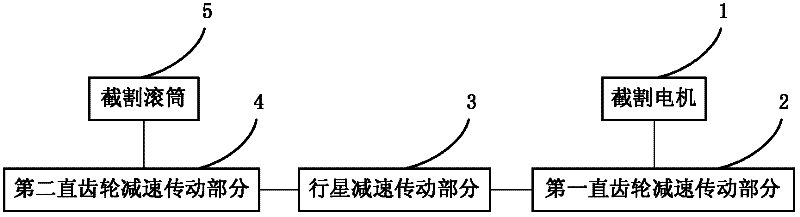
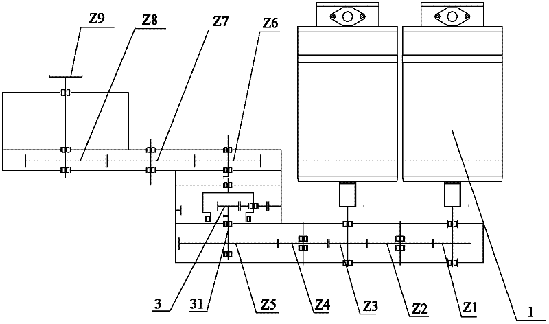
[0019] Please refer to figure 1 and figure 2 , figure 1 A block diagram of the rocker arm transmission system of a coal mining machine provided by the embodiment of the present invention, figure 2 for figure 1 The specific structural schematic diagram of the rocker arm transmission system of the shearer is shown (the cutting drum is omitted). Combine below figure 1 and figure 2 The rocker arm transmission system of the coal shearer is described in detail.

[0020] As shown in the figu...


PUM


Abstract

The invention relates to the field of mining machinery, and discloses a coal cutter and a rocker arm transmission system thereof. The rocker arm transmission system is arranged between a cutting roller and a cutting motor. The rocker arm transmission system comprises a first spur gear speed-reducing transmission part connected to the cutting motor, a second spur gear speed-reducing transmission part connected to the cutting roller, and a planet gear speed-reducing transmission part arranged between the first spur gear speed-reducing transmission part and the second spur gear speed-reducing transmission part. The rocker arm transmission system of the coal cutter has the advantage that the planet gear speed-reducing transmission part is arranged between the first spur gear speed-reducing transmission part and the second spur gear speed-reducing transmission part, and thus the rocker arm transmission system has a large transmission ratio; a rotating speed and a line speed of the cutting roller are reduced; a working face environment of the coal cutter is improved; a size of a structure cooperating with a cutting roller hub is reduced; the length of a cutting roller blade is increased; and coaling effects and coaling efficiency of a thin coal layer are improved.

Description

technical field [0001] The invention relates to the technical field of engineering machinery, in particular to a coal shearer rocker arm transmission system. The invention also relates to a coal shearer with the above-mentioned rocker arm transmission system of the coal shearer. Background technique [0002] In order to meet the needs of modern high-yield and high-efficiency coal mining, currently domestic and foreign thin and medium-thin coal seam shearers have put forward higher requirements for cutting power, but the increase in motor power and diameter will affect the coal clearance of the shearer , coal loading effect and the height of the machine surface, therefore, domestic manufacturers generally use double cutting motor rocker arms, and now this form of rocker arms has been widely used in thin coal seam and medium thin coal seam shearers. The increase of cutting power brings difficulties to the layout of the rocker arm transmission system of the shearer. The existi...

Claims


Application Information

Patent Timeline
Patent Type & Authority Applications(China)
IPC IPC(8): E21C31/02E21C25/06F16H1/28
Inventor 苑雪涛申磊龚在清赵永生李庆茹
Owner SANY HEAVY EQUIP
Why Eureka
Try Eureka