
Integral combined-type heat absorber of solar thermomotor

A heat absorber and heat engine technology, which is applied in the field of integral combined heat absorbers, can solve the problems of absorbing solar radiation energy loss, high technical difficulty of processing technology, and influence of heat absorption effect, and achieve reliable processing technology and gas heat exchange Good effect, convenient for mass production

Inactive Publication Date: 2012-05-02
TIANJIN GREEN ENERGY TONGHUI TECH
View PDF1 Cites 3 Cited by
  • Summary
  • Abstract
  • Description
  • Claims
  • Application Information

AI Technical Summary

Problems solved by technology

Due to the limitation of pipe layout, the heat absorber of this structure has to design a round hole in the center, which is used to place a heat protection cone that does not directly absorb heat, which directly brings disadvantages to the heat absorption effect. influences
At the same time, since the circumference of the outer ring of the circular heater becomes larger, the distance between the tubes is closer at the center of the circle, and there will be a certain distance away from the center of the circle, so there will inevitably be gaps, which will definitely have a negative impact on the absorption of solar radiation energy. certain loss
In addition, the complex shape of many thin tubes of various shapes brings high technical difficulty to the processing technology, as well as problems such as more processing man-hours and higher mold costs.

Method used


Image

  • Integral combined-type heat absorber of solar thermomotor
  • Integral combined-type heat absorber of solar thermomotor
  • Integral combined-type heat absorber of solar thermomotor

Examples


Embodiment Construction

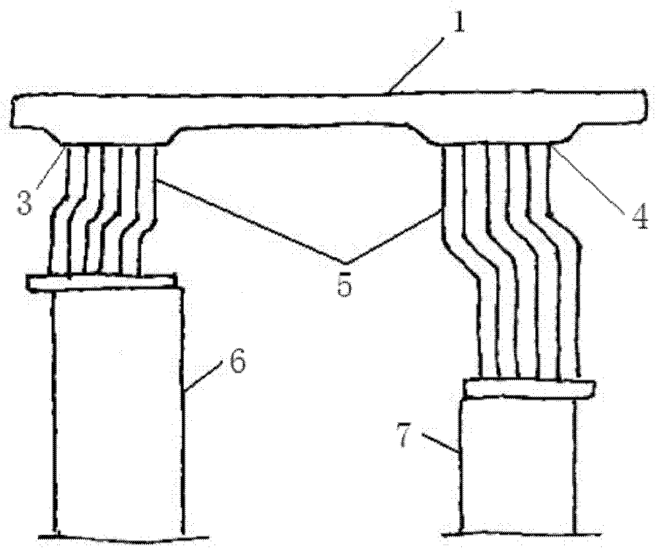
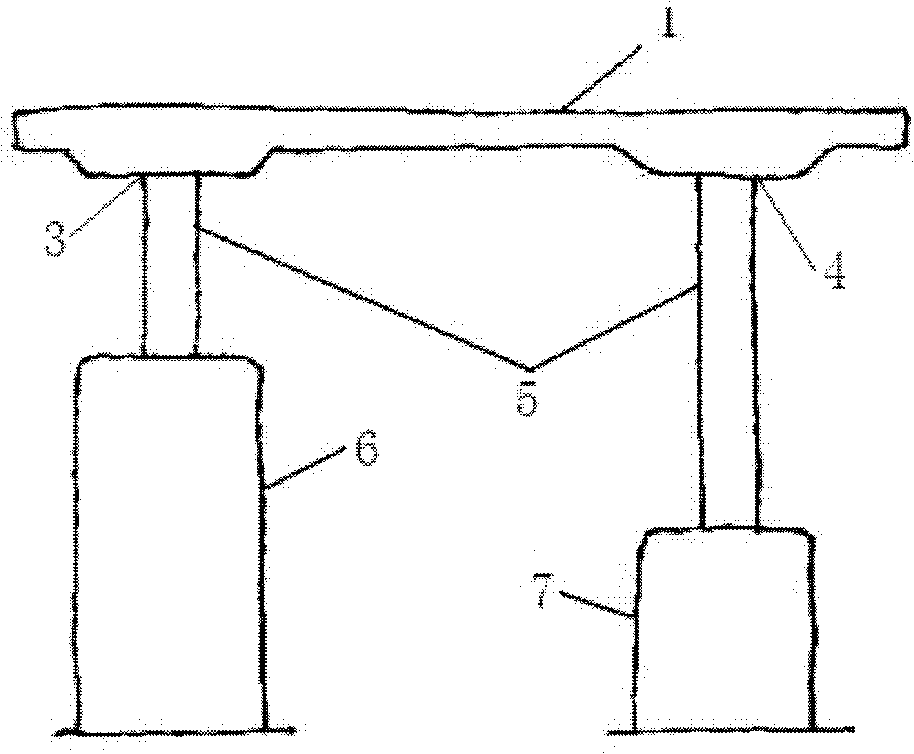
[0032] The integral combined heat absorber of the solar energy heater of the present invention will be described in detail below in conjunction with the embodiments and accompanying drawings.

[0033] The heat absorber device involved in the present invention is generally located at the front of the solar heat engine, that is, near the focus of the solar concentrator, and it essentially belongs to a gas heat exchanger that absorbs solar radiant heat.

[0034] The front side of the combined overall heat absorber faces the solar concentrating mirror and absorbs the radiant heat reflected by the mirror. In order to reduce the heat dissipation loss of the heat absorber, it is necessary to set an outer cover with heat preservation function around it, also called a heat collecting chamber. At the same time, the back of the heat absorber is also provided with thermal insulation material, which not only serves as heat protection for the rear parts, but also plays a role of heat insula...


PUM


Abstract

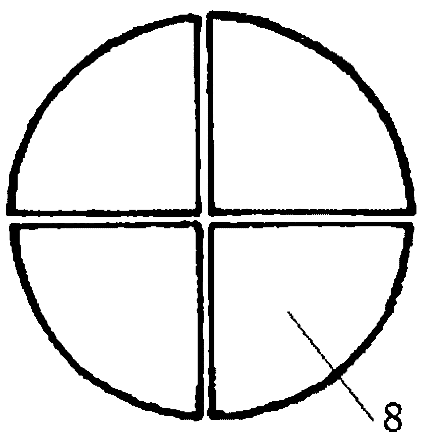
The invention discloses an integral combined-type heat absorber of a solar thermomotor, wherein the heat absorber is provided with a plurality of fluid channels, fluid inlets and fluid outlets; the plurality of fluid channels are formed in a heat absorber body; the fluid inlets and the fluid outlets are formed on the surface of the heat absorber body and are respectively and correspondingly communicated with ports of two ends of each fluid channel in the heat absorber body; the fluid inlets are connected with an air cylinder through a connecting pipeline; the fluid outlets are connected with a heat regenerator through a connecting pipeline; the outer surface of the heat absorber body is a plane or a corrugated plane; the plurality of fluid channels in the heat absorber body and the heat absorber body are formed by integral casting; the heat absorber body is formed by the welding of two symmetrical plate bodies up and down; and the plurality of fluid channels are formed by the butt joint of symmetrical semi-round channel grooves on opposite surfaces of the two plate bodies which are symmetrical up and down. According to the invention, the heat absorber of the thermomotor is designed into a round integral combined-type heat absorber, or a circle is spliced by four fan-shaped objects of 90 degrees, thus solar condensation radiation heat is absorbed, the appearance is simple, the processing technology is reliable, mass production is convenient, and the cost is low.

Description

technical field [0001] The invention relates to a heat absorbing device for a solar heat machine. In particular, it relates to an integral combined heat absorber of a solar heat engine capable of effectively absorbing the concentrated radiant heat of the sun. Background technique [0002] The heat absorber is one of the important components of the solar heat engine (also known as the solar Stirling engine). Its heat transfer effect and ability to withstand high temperature and high pressure have a direct and significant impact on energy conversion efficiency, overall machine output and work reliability. Generally, for the consideration of high temperature and high pressure resistance, the heat absorber of a solar heat generator is mostly composed of densely arranged small-diameter pipes. Due to the limitation of pipe layout, the heat absorber of this structure has to design a round hole in the center, which is used to place a heat protection cone that does not directly abs...

Claims


Application Information

Patent Timeline
IPC IPC(8): F02G1/055
Inventor 王智勇
Owner TIANJIN GREEN ENERGY TONGHUI TECH
Learn More