
Medical laser treatment device and method utilizing total reflection induced by radiation

A technology of optical radiation and laser radiation, applied in the field of laser systems, can solve problems such as large probe diameter, reduced bonding between end cap and glass optical fiber, and bulky optical fiber probe

Inactive Publication Date: 2012-05-02
BIOLITEC UNTERNEHMENSBETEILLIGUNGS II AG
View PDF11 Cites 9 Cited by
  • Summary
  • Abstract
  • Description
  • Claims
  • Application Information

AI Technical Summary

Problems solved by technology

Consequently, the distal ends of those fiber optic probes are often bulky and difficult to produce
Furthermore, the bond between the end cap and the glass fiber can be compromised by the reduced damage threshold, especially if the fiber is glued to the end cap and the treatment requires high optical energy
Additionally, many of these inventions require relatively large probe diameters

Method used


Image

  • Medical laser treatment device and method utilizing total reflection induced by radiation
  • Medical laser treatment device and method utilizing total reflection induced by radiation
  • Medical laser treatment device and method utilizing total reflection induced by radiation

Examples


example 1

[0026] Example 1 - Glass Fiber with Conical Fiber Tip

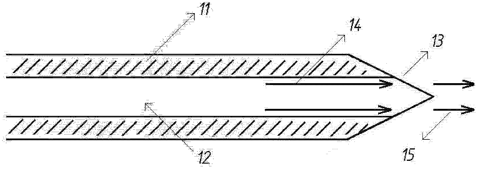
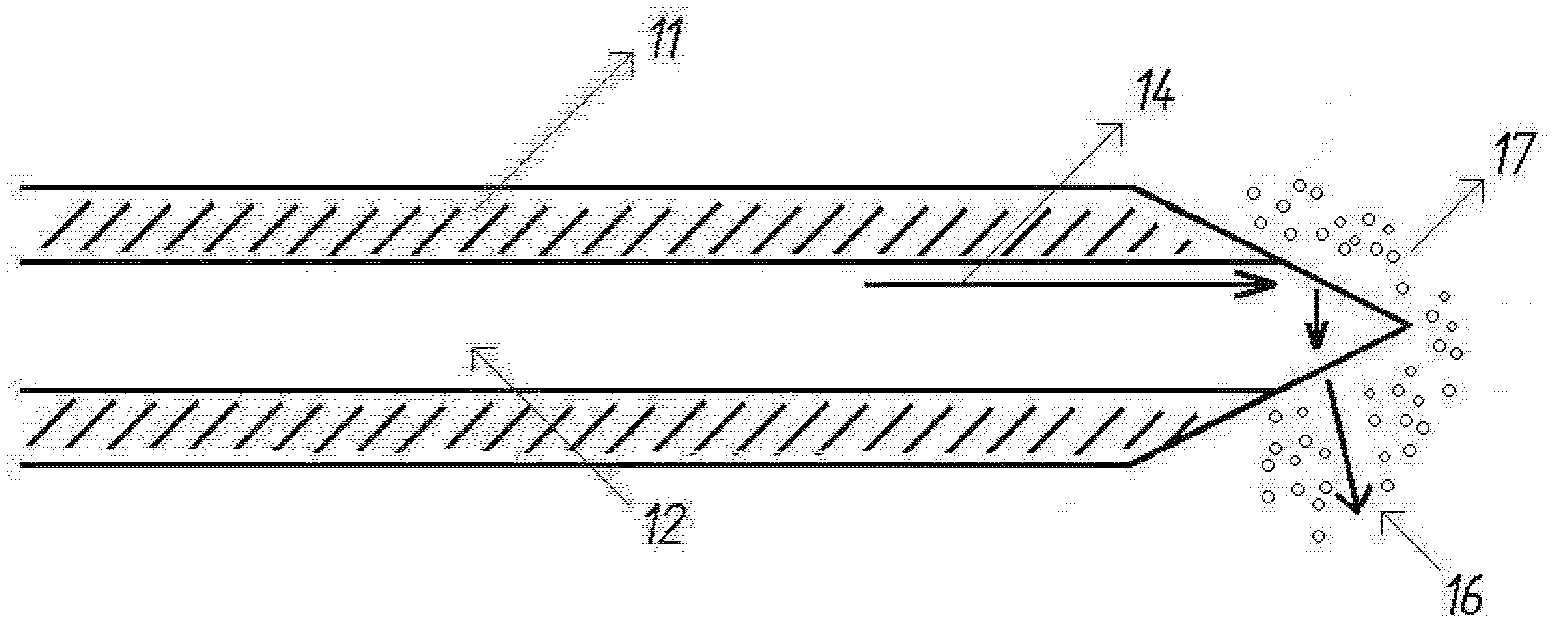
[0027] Figure 1a and 1b A preferred embodiment is schematically depicted comprising a glass optical fiber having a refractive index n1 The fiber core (12) and the refractive index n 2 Fiber cladding (11), where n 2 less than n 1 . The optical fiber distal tip (13) has a conical shape.

[0028] When such a probe is surrounded by an aqueous solution (for example, in a vessel supplied with blood), the majority of the optical radiation (14) transmitted inside the fiber core will propagate through the conical fiber tip and as Figure 1a Emitted in the forward direction (15) as shown in .

[0029] Such as Figure 1b As depicted in , the optical power emitted in the forward direction is absorbed by the surrounding liquid medium, which evaporates and thus forms vapor bubbles (17 ). Since the refractive index of water vapor is significantly lower than that of liquid water, the refractive index gradient between the fiber ma...

example 2

[0031] Example 2 - Glass Fiber with Bent Fiber Tip

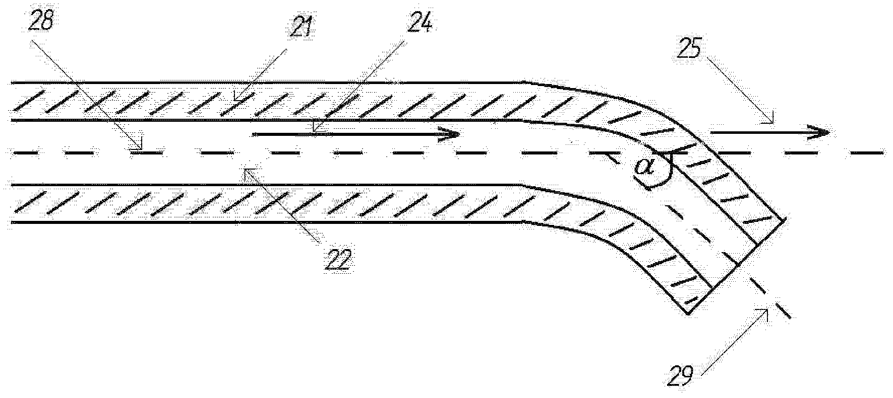
[0032] Figure 2a and 2b Schematically depicts a preferred embodiment comprising a glass optical fiber having a refractive index n 1 The fiber core (22) and the refractive index n 2 Fiber cladding (21), where n 2 less than n 1 . The fiber tip is bent laterally to deviate from the long axis of the fiber axis. The fiber axis (28) forms an angle α with the normal (29) to the end face of the light. Usually, the value of α is about 20-35°.

[0033] Figure 2a The majority of the illustrated optical power (25) travels in the forward direction.

example 3

[0034] Example 3 - Optical fiber with beveled tip

[0035] Another preferred embodiment is a fiber with a beveled fiber tip, such as Figure 3a and Figure 3b shown in . Laser radiation (34) propagates through the fiber core (32) by means of total internal reflection at the core / cladding interface where the fiber cladding (31) has a higher refractive index (n 1 ) low refractive index n 2 .

[0036] Since the refractive index of the surrounding aqueous solution is lower than n 1 But greater than the refractive index of air or even water vapor, so the laser light is emitted through the beveled head (33) in a straight-ahead direction (35). Once the laser radiation (35) evaporates a specified amount of aqueous solution and creates vapor bubbles (37), the refractive index gradient between the fiber core and its surroundings is changed. The refractive index of the evaporated aqueous solution (37) is low enough that near total reflection occurs at the core / vapor interface. Thu...


PUM


Abstract

A device is provided for improved surgical procedures to remove unwanted or hyperplasic tissue from a patient. In particular, laser ablation, urological treatments, benign prostatic hyperplasia treatments and other applications benefit from the device. Specially prepared optical waveguide tips allow for enhanced irradiation of desired tissues with light sources including laser diodes, bright LEDs or lamps. The refractive indices of the waveguide materials and the surrounding medium are such that a significant fraction of the optical radiation, being transported in the waveguide, is coupled out of the waveguide into the surrounding medium through a peripheral surface at or near the distal end.; The optical radiation is chosen to have an appropriate wavelength and sufficient power density, so that the surrounding medium will be changed in the vicinity of at least a part of the peripheral surface area. The changes of the surrounding medium result in a change of its refractive index such that the optical radiation is redirected. Device is particularly useful for treatments within a patient where entry and / or treatment space is limited / restricted.

Description

[0001] Domestic priority under 35USC 119(e) [0002] This application claims an invention titled "Medical laser treatment device and method utilizing total reflection induced by radiation" submitted by Wolfgang Neuberger and Walter Cecchetti on April 9, 2009 benefit and priority of U.S. Provisional Application No. 61 / 168,099, which is incorporated herein by reference. technical field [0003] The present invention relates to a laser system for medical treatment, and in particular, to laser surgery. More specifically, it relates to fiber optic systems and methods for the surgical treatment of various medical conditions, including benign prostatic hyperplasia (BPH). Background technique [0004] Many medical applications (eg, endoluminal treatment of varicose veins, laser treatment of BPH or hemorrhoids) require treatment of a target tissue area not directly in front of the fiber optic, but to the side. Since many of these therapies must be performed in vivo within an enviro...

Claims


Application Information

Patent Timeline
IPC IPC(8): A61B18/20A61N5/067
CPCA61B2018/00005A61B18/22A61B2017/00274A61B2018/2288A61B2018/2272A61B2018/00547
Inventor 沃尔夫冈·纽伯格沃尔特·岑希提
Owner BIOLITEC UNTERNEHMENSBETEILLIGUNGS II AG
Learn More