Method for recovering oil gas and device

A recovery method and technology for oil and gas, applied in separation methods, transportation and packaging, chemical instruments and methods, etc., can solve the problems of increasing the operating cost of the combined condensation-adsorption process, local overheating of the activated carbon bed, and reducing the service life of the adsorbent, etc. Achieve the effect of reducing the scale of subsequent processing units, eliminating potential safety hazards, and reducing volatilization of oil and gas

Inactive Publication Date: 2012-05-09
CHINA PETROLEUM & CHEM CORP +1
View PDF7 Cites 22 Cited by
  • Summary
  • Abstract
  • Description
  • Claims
  • Application Information

AI Technical Summary

Problems solved by technology

When activated carbon adsorbs oil and gas components, the adsorption and heat release will cause a large temperature rise in the activated carbon bed, especially when the concentration of oil and gas is high, the activated carbon bed is prone to local overheating, thereby reducing the service life of the adsorbent and making the operation There are safety hazards in the process
[0004] CN1494454A discloses a device that adopts activated carbon adsorption method to recover organic matter. After the adsorption stops, the organic components are desorbed and adsorbed by steam, and then enter the condenser to condense and recover, and a large amount of steam is introduced to condense, which increases the operating cost of the device
CN1522785 discloses a method for recovering oil and gas, which compresses and cools the oil and gas, and absorbs it under pressurized conditions. Difficult to operate stably
Due to the mixture of desorbed oil and gas and collected oil and gas, oil and gas back-mixing reduces the dew point of desorbed oil and gas, requiring a lower condensation temperature, which greatly increases the operating cost of this condensation-adsorption combined process

Method used


Image

  • Method for recovering oil gas and device
  • Method for recovering oil gas and device

Examples


Embodiment

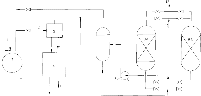
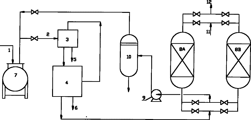
[0027] Such as figure 1 As shown, in the oil and gas recovery method of the present invention, oil gas 2 is collected and cooled by cooling device 3 through heat exchange, cooling device condensate 5 is recovered, and the cooled oil gas enters condensing device 4, and part C in the oil gas is 2 and most of the C 3 and the above hydrocarbon components are condensed, and the condensate 6 of the condensing unit is recovered. The uncondensed oil gas returns to the cooling device 3 as the cooling medium of the cooling device 3 . The uncondensed oil gas enters the adsorption tower 8 to absorb the oil gas after being exchanged by the cooling device 3, and the adsorption tail gas 12 is discharged up to the standard. At least two adsorption towers 8 are provided for switching operation. The saturated adsorption tower 8 is desorbed and regenerated by a vacuum pump 9 , and the regenerated oil gas desorbed by vacuum is sent to the desorbed oil gas storage tank 10 . When the oil product...


PUM


Abstract

The invention relates to a method for recovering oil gas and a device. Oil gas exhausted from an oil product storage device is firstly condensed; condensate is recovered; uncondensed gas phase enters an adsorption device for adsorption; after being in adsorption saturation, the adsorption device is regenerated by adopting a vacuum regeneration manner; and concentrated oil generated by vacuum regeneration is recycled to the oil product storage device. According to the method and the device, provided by the invention, the oil gas is recovered by combining the mode of returning the oil gas to the oil product storage device and an oil gas recovery technology, desorbed oil gas is returned to the gas-liquid balanced system of the oil product storage device, the partial pressure of the oil gas is increased, and the loss of an oil product, caused by evaporating, is fundamentally reduced. The method and the device, provided by the invention, have the characteristics of large operating flexibility, low energy consumption, small investment, no potential safety hazard, reachability in tail gas emission standards, and the like.

Description

technical field [0001] The present invention relates to an oil and gas recovery method and device in the technical field of environmental protection and energy saving, in particular to an oil and gas recovery method and device for recovering hydrocarbons from volatilized oil and gas in the process of loading and unloading light oil products and making exhaust gas meet the discharge standard . Background technique [0002] During the storage, transportation and sales of light oil products, a large amount of oil and gas escapes. According to statistics, the oil products lost by the escape of light oil products account for about 0.5% of the light oil products every year. On the one hand, this leads to a large amount of waste of oil and gas resources, reducing the economic benefits of enterprises, and on the other hand, it leads to serious environmental pollution. In addition, since oil and air easily form explosive mixtures (the lower explosion limit is generally 1% to 6%), t...

Claims


Application Information

Patent Timeline
Patent Type & Authority Applications(China)
IPC IPC(8): B01D53/02B01D5/00B65D90/30
Inventor 廖昌建刘忠生王海波李经纬王明星
Owner CHINA PETROLEUM & CHEM CORP
Why Eureka
Try Eureka