Single-horizontal shaft vibration stirrer

A vibrating mixing and mixer technology, which is applied to cement mixing devices, clay preparation devices, chemical instruments and methods, etc., can solve the problems affecting the operation quality and efficiency of mixing equipment, the difficulty of achieving microscopic uniformity of the mixture, and the inability to obtain good mixing. and other problems, to achieve the effect of improving the low-efficiency area of ​​stirring, easy to ensure bearing life, and simple structure

Active Publication Date: 2012-05-09
德通智能科技股份有限公司
View PDF11 Cites 11 Cited by
  • Summary
  • Abstract
  • Description
  • Claims
  • Application Information

AI Technical Summary

Problems solved by technology

[0004] At present, the single horizontal shaft mixer is a kind of forced mixer that is often used in concrete mixing work. It also has the problem that the mixture is difficult to achieve microscopic uniformity, and when the mixing device is working, the speed near the center of the circular mixing drum Low, high velocity at the barrel wall
In order not to cause segregation of concrete materials, the maximum linear velocity of the mixing blade must be limited, generally within 1.8m / s. Therefore, at the end of the mixing arm close to the stirring shaft, due to the relatively low linear velocity, the stirring effect of the material is very strong. Weak, it forms a stirring inefficient zone, or even a stirring dead zone
This not only delays the working time of the whole machine, but also leaves quality problems, and the fluidity of the mixture in the low-efficiency area is poor, and it is easy to adhere to the stirring shaft, resulting in shaft holding phenomenon.
With the continuous development of large-scale mixers, the capacity of the mixing drum is getting larger and larger, and the radius of the mixing drum is much larger than the height of the mixing blades. In this way, when the mixer is working, the mixing blades can only stir a layer of material close to the inner wall of the mixing drum, while The material between the stirring blade and the central stirring shaft cannot be well stirred
Therefore, the problem of the low-efficiency mixing zone of the large-capacity mixing drum is particularly prominent, and the low-efficiency mixing zone is an inherent defect of the conventional forced mixer structure, which seriously affects the operation quality and efficiency of the mixing equipment.

Method used


Image

  • Single-horizontal shaft vibration stirrer
  • Single-horizontal shaft vibration stirrer
  • Single-horizontal shaft vibration stirrer

Examples


Embodiment 1

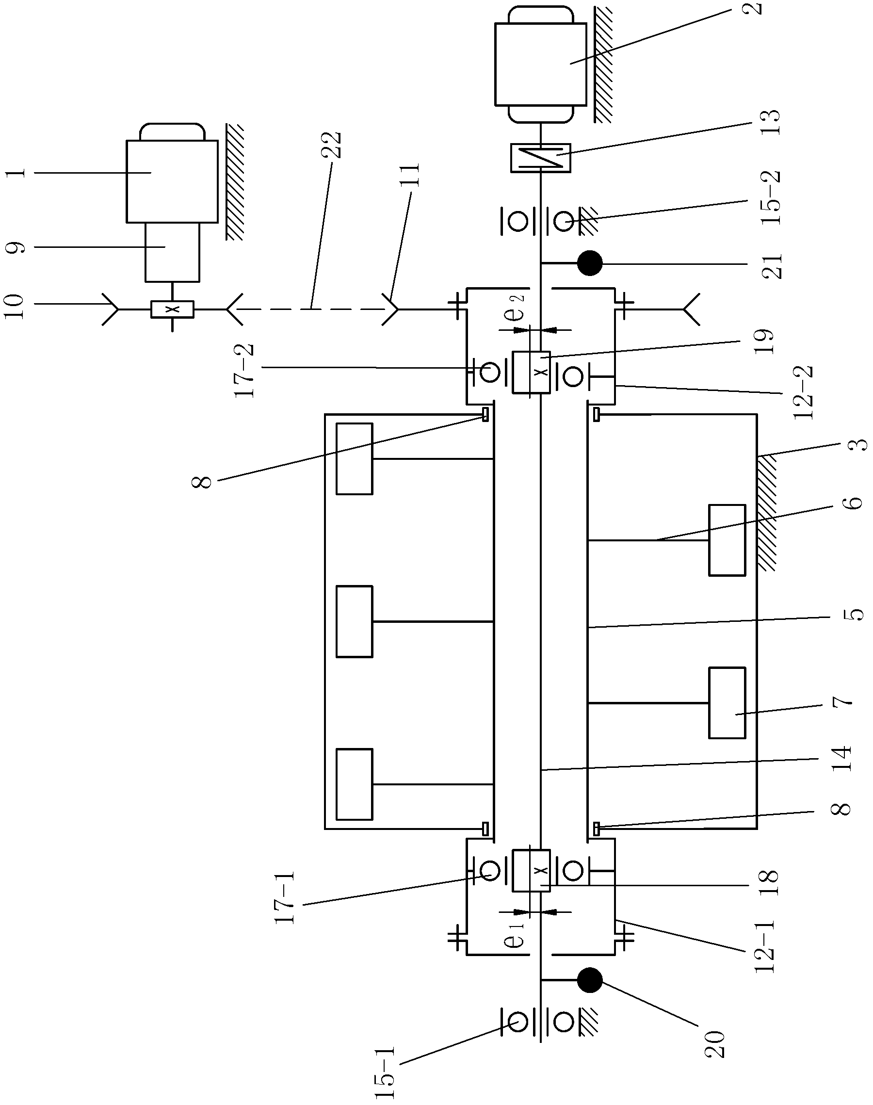
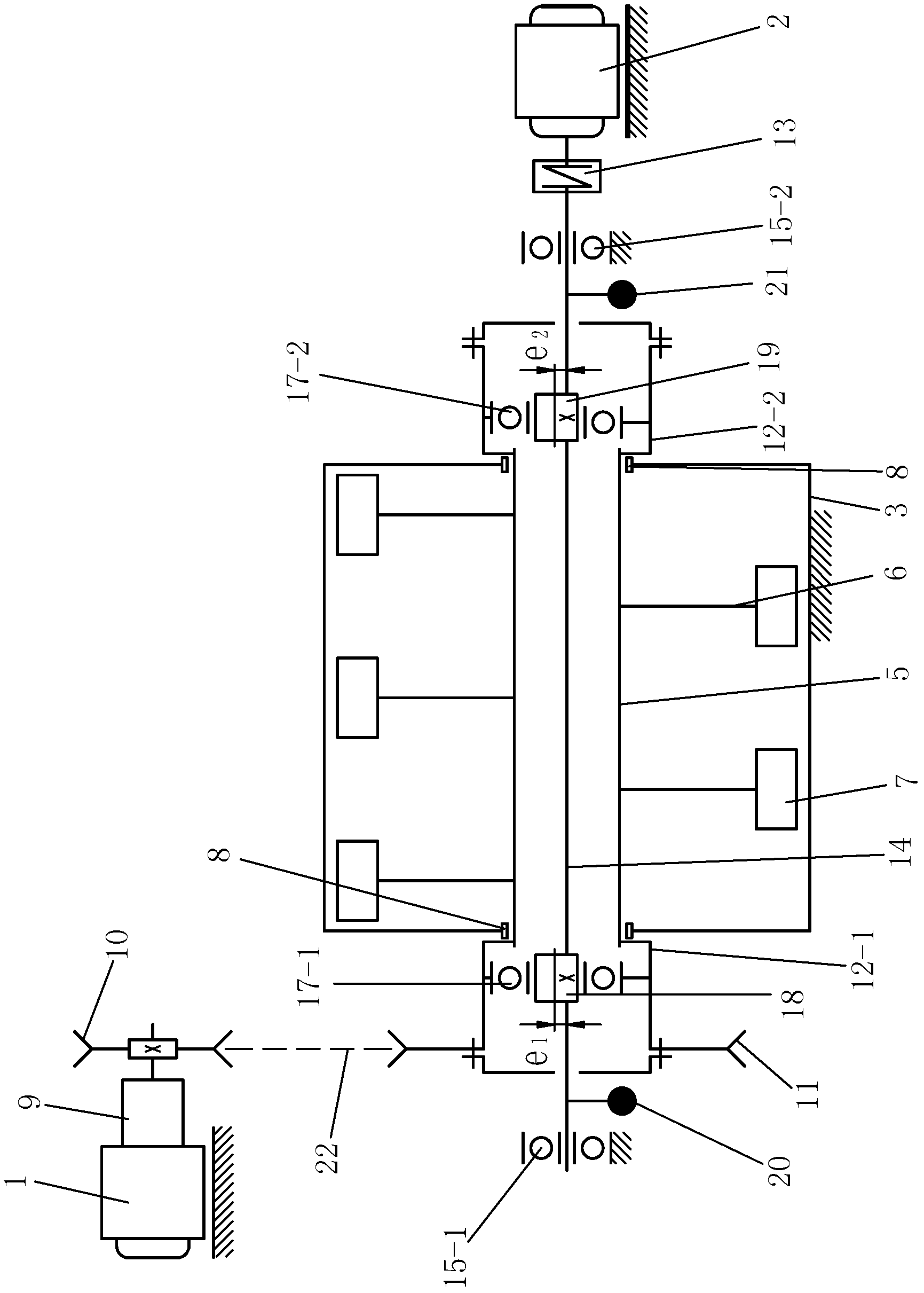
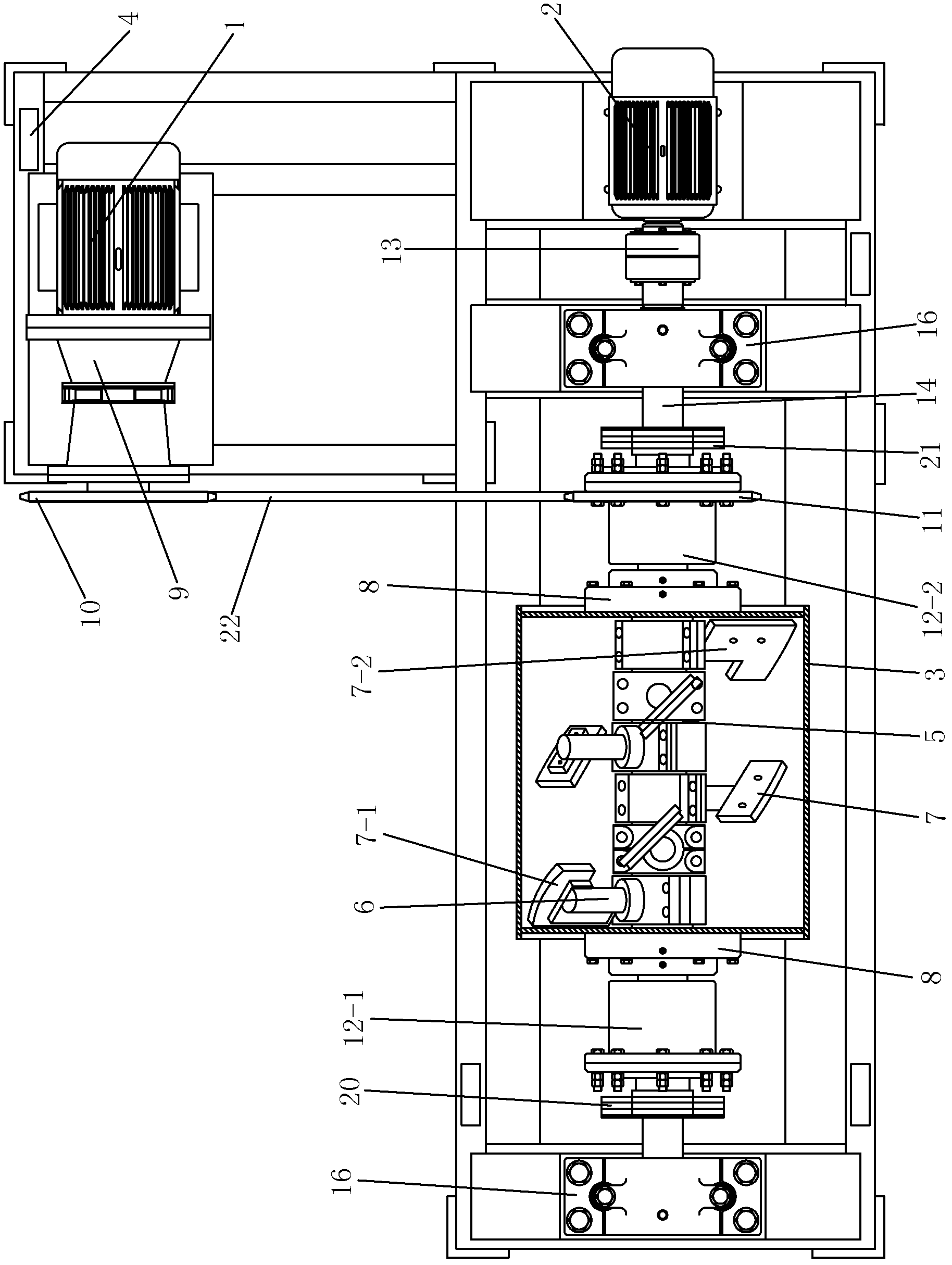
[0030] Such as figure 1 , image 3 , Figure 4 and Figure 5As shown, a single-horizontal shaft vibratory mixer includes a frame 4, a stirring transmission device, a vibration transmission device, a vibration stirring device, a stirring drive motor 1 and a vibration drive motor 2, and the stirring drive motor 1 and the vibration drive motor 2 are both Set on one side of the vibration stirring device or the stirring drive motor 1 and the vibration driving motor 2 are respectively arranged on both sides of the vibration stirring device, the stirring drive motor 1 passes through the stirring transmission device and the vibration stirring device Connect and drive the vibration stirring device to stir, the vibration driving motor 2 is connected with the vibration stirring device through the vibration transmission device and drives the vibration stirring device to generate vibration, the stirring driving motor 1 and the vibration driving motor 2 are fixed on the frame 4 The vibra...

Embodiment 2

[0042] The difference from Embodiment 1 is that the stirring drive motor 1 and the vibration drive motor 2 are respectively arranged on both sides of the vibration stirring device, and the large sprocket 11 is fixedly installed on the outer wall of the first stirring sleeve 12-1 On, the output shaft of described vibration drive motor 2 is connected with the left end of vibration shaft 14 through coupling 13 (as figure 2 shown).

[0043] The working process of the present invention is: after putting each raw material that concrete is formed into in the mixing drum 3, start the stirring drive motor 1 and the vibration drive motor 2 simultaneously or delay starting the vibration drive motor 2 after starting the stirring drive motor 1 for a few seconds, then stir The driving motor 1 outputs stirring power, drives the small sprocket 10 to rotate through the reducer 9, and then drives the large sprocket 11 and the stirring sleeve 12 fixedly connected to it to rotate through the cha...


PUM


Abstract

The invention discloses a single-horizontal shaft vibration stirrer, which comprises a frame, a stirring transmission device, a vibration transmission device, a vibration stirring device, a stirring driving motor and a vibration driving motor; the stirring driving motor and the vibration driving motor are provided at one side of the vibration stirring device or respectively provided at two sides of the vibration stirring device, the stirring driving motor is connected with the vibration stirring device through the stirring transmission device, the vibration driving motor is connected with the vibration stirring device through the vibration transmission device; the vibration stirring device comprises a stirring drum which is fixedly mounted on the frame and a stirring mechanism which is horizontally arranged on the revolution center of the stirring drum, the stirring mechanism comprises a hollow stirrer shaft arranged in the stirring drum through a bearing and a plurality of stirring units which are fixedly mounted on the outer wall of the hollow stirrer shaft. The invention has the advantages of simple structure, reasonable design, and convenient usage and operation, the concrete mixture can reach uniformness on macroscopic view or microscopic view in short time, and the low stirring efficiency zone near the stirrer shaft is improved.

Description

technical field [0001] The invention relates to a mixer, in particular to a single-horizontal-shaft vibration mixer mainly suitable for mixing concrete. Background technique [0002] The mixer is the main equipment for concrete mixing. Its function is to mix the prepared materials into a uniform and quality mixture. According to the working principle, it can be divided into two categories: self-falling mixer and forced mixer. The self-falling mixer uses a stirring device to divide and lift the material in the mixing drum until the friction between the material and the stirring device is less than the component of gravity that makes the material slide down, and the material falls by its own weight, so that the parts of the material fall. The mutual position is continuously redistributed to obtain uniform mixing. The power consumption of this mixer and the wear of wearing parts are small, but the mixing intensity is not strong enough. Generally, it is only suitable for mixing ...

Claims


Application Information

Patent Timeline
IPC IPC(8): B28C5/14B28C5/48
Inventor 冯忠绪赵利军陈卫
Owner 德通智能科技股份有限公司
Why Eureka
Try Eureka