
Heat exchange tube unit, finned tube air-cooled condenser and cooling air evaporator

A technology of heat exchange tubes and monomers, applied in evaporators/condensers, tubular elements, refrigeration and liquefaction, etc., can solve the problems of performance degradation of refrigeration systems, increased loss of refrigerant flow resistance, high product costs, etc. Cost, reduction of flow loss, effect of reduction in metal consumption

Inactive Publication Date: 2012-05-09
TIANJIN UNIV OF COMMERCE
View PDF7 Cites 12 Cited by
  • Summary
  • Abstract
  • Description
  • Claims
  • Application Information

AI Technical Summary

Problems solved by technology

Since the specific volume of the refrigerant gradually decreases in the process of condensing into a liquid after releasing heat in the heat exchange tube, only a part of the internal space of the heat exchange tube is used, resulting in the consumption of excess metal materials for the heat exchange tube in the excess space, and the product cost is high.
For the finned tube cooling air evaporator composed of multiple heat exchange tube units, since the refrigerant absorbs the heat of the external air in the heat exchange tube, the specific volume gradually increases in the process of evaporation and gasification, and the diameter of the heat exchange tube is not the same. Change, the flow resistance loss of the refrigerant increases, resulting in a decrease in the suction pressure of the refrigeration compressor, an increase in the pressure ratio, an increase in power consumption, and a decrease in the performance of the refrigeration system

Method used


Image

  • Heat exchange tube unit, finned tube air-cooled condenser and cooling air evaporator
  • Heat exchange tube unit, finned tube air-cooled condenser and cooling air evaporator
  • Heat exchange tube unit, finned tube air-cooled condenser and cooling air evaporator

Examples


Embodiment Construction

[0022] The present invention will be described in detail below with reference to the drawings and specific embodiments.

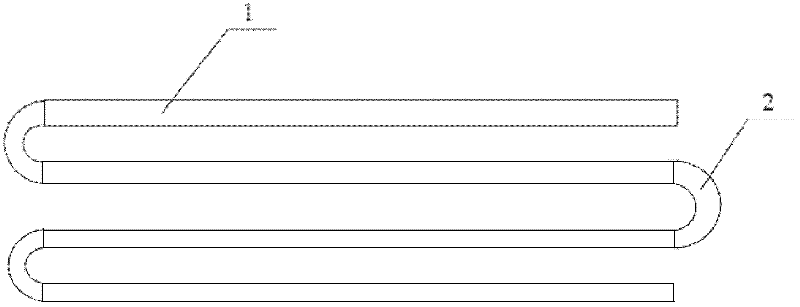
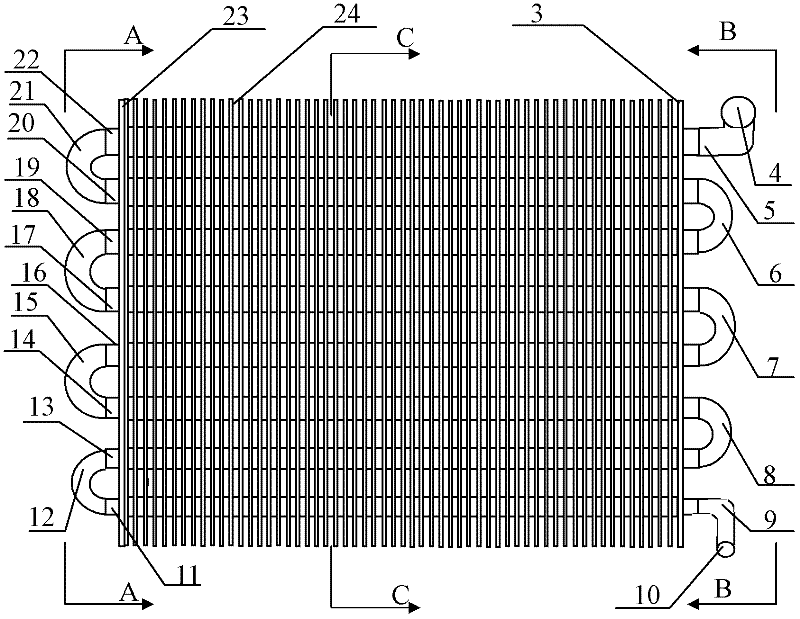
[0023] figure 1 It is a schematic diagram of the heat exchange tube unit of the present invention, including a plurality of heat exchange tube monomers 1 arranged in parallel. The heat exchange tube monomers are connected end to end through elbows 2 to form heat exchange medium channels, adjacent to each other in the direction of increasing gas specific volume The diameter of the arranged heat exchange tube monomers gradually increases, and the bends used for the end to end connection of the heat exchange tube monomers are tapered elbows.

[0024] The heat exchange tube unit of the present invention can be composed of air-cooled condensers, cooling air evaporators and other products according to the needs of the use environment. The heat exchange tube units can be arranged horizontally or vertically, and the heat exchange tube monomers in the heat exchange tube u...


PUM


Abstract

The invention discloses a heat exchange tube unit, a finned tube air-cooled condenser and a cooling air evaporator, and aims to provide the heat exchange tube unit in which heat exchange tube monomers and connecting elbows change as the change of the specific volume of a refrigerant in the heat exchange tube, the air-cooled condenser and the cooling air evaporator. The heat exchange tube unit comprises a plurality of heat exchange tube monomers which are parallelly arranged, wherein the heat exchange tube monomers are connected end to end to form a heat exchange medium channel through the elbows, the diameters of the heat exchange tube monomers which are adjacently arranged along the direction in which the specific volume of gas increases gradually increase, and the elbows are gradually diameter-changing elbows. The diameters of the heat exchange tube monomers which are adjacently arranged along the direction from a gas inlet tube to a liquid collecting tube in the air-cooled evaporator gradually decrease, and the elbows are gradually reducing elbows. The diameters of the heat exchange tube monomers which are adjacently arranged along the direction from a liquid distributing tube to a gas collecting tube in the air-cooled evaporator gradually increase, and the elbows are gradually diameter-expanding elbows. For the condenser, the metal consumption can be reduced. For the evaporator, the flow losses can be reduced.

Description

Technical field [0001] The present invention relates to the technical field of refrigeration, and more specifically, to a heat exchange tube unit with a gradually changing diameter and a finned tube condenser connected by a tapered elbow and a fin connected by a tapered elbow. Cooling air evaporator. Background technique [0002] In the refrigeration field, the heat exchange tube unit is formed by connecting multiple parallel heat exchange tube monomers through elbows. The size of the heat exchange tube is the same, and the size of the connecting elbow is the same. For a finned tube condenser composed of multiple heat exchange tube units, the flow from the refrigerant gas entering the heat exchange tube of the condensation heat exchanger to the heat exchange tube condensing into liquid out of the condensation heat exchanger The dimensions of the channels are the same. As the specific volume of the refrigerant gradually decreases during the process of condensing into a liquid af...

Claims


Application Information

Patent Timeline
IPC IPC(8): F28F1/00F25B39/04F25B39/02
Inventor 宁静红刘圣春叶庆银
Owner TIANJIN UNIV OF COMMERCE
Learn More