
Microstructure fiber sensor

A microstructure optical fiber and sensor technology, applied in the field of biochemical sensing, can solve the problems of not being able to meet the detection requirements, not being able to realize a large-scale measurement, and the detection range of SPR sensors being limited, etc., to achieve a simple and stable structure, and to solve the problem of sample packaging Difficult, Small Effects

Active Publication Date: 2012-05-09
HUAZHONG UNIV OF SCI & TECH
View PDF3 Cites 13 Cited by
  • Summary
  • Abstract
  • Description
  • Claims
  • Application Information

AI Technical Summary

Problems solved by technology

[0003] However, with the rapid development of biology, chemistry, medicine, agriculture, environmental monitoring and related fields, the scope of research is expanding day by day. Since the detection range of the SPR sensor is limited by the background material of the detector itself, it can only detect materials with a refractive index lower than the background material. Samples below the refractive index cannot be measured in a large range, and the traditional SPR sensor can no longer meet the detection requirements

Method used

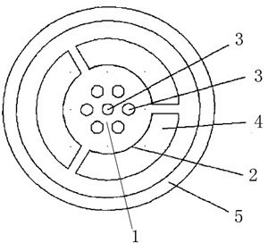

Image

  • Microstructure fiber sensor
  • Microstructure fiber sensor
  • Microstructure fiber sensor

Examples


Embodiment Construction

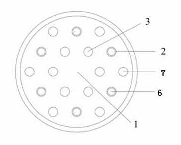
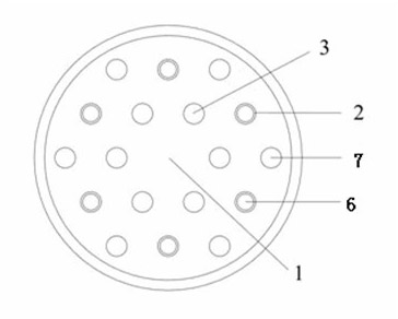
[0022] like figure 2 As shown, the core 1 of the microstructured optical fiber of the present invention is surrounded by two circles of air holes, wherein there are 12 air holes in the outer circle, 6 air holes 3 in the inner circle, 6 coated holes in the outer circle and non-coated holes in the outer circle The number of 7 is 6 respectively. The air holes in the inner ring and outer ring are arranged symmetrically with the center of the fiber core; the center points of the air holes in the outer ring are connected in a straight line to form a hexagon, and the center points of the air holes in the inner ring are connected in a straight line to form a hexagon . The hexagon of the line connecting the center points of the air holes of the outer ring is similar to and parallel to the hexagon of the line connecting the center points of the air holes of the inner ring. Both the coated hole 6 of the outer ring and the non-coated hole 7 of the outer ring are sample channels. In th...


PUM


Abstract

The invention relates to a microstructure fiber sensor in the field of biochemistry sensing. The microstructure fiber includes an inner ring of air apertures and an outer ring of air apertures; the outer ring air apertures comprise two varieties of apertures of inner film plated apertures and non-inner film plated apertures, which are respectively used as sample channels. The outer ring film plated apertures are used as SPR detection channels for measuring a sample with a refractive index lower than that of a background fiber material. The outer ring non-film plated apertures are used for detecting a sample with a refractive index higher than that of the background fiber material. The inner ring air apertures and the outer ring air apertures, and the outer ring film plated apertures and non-film plated apertures are in a periodically arranged aperture array structure, so as to realize two detection mechanisms of surface plasmon resonance and coupling resonance in one structure; therefore, detection scope of a sensor is effectively expanded and not restrained by the sensor background material any more, thereby satisfying wider application demand. The invention also has advantages of small volume, simple structure and easiness for packaging.

Description

technical field [0001] The invention relates to the field of biochemical sensing, in particular to a biochemical sensor based on the principle of surface plasmon resonance and the principle of resonance coupling. Background technique [0002] The discovery of the Surface Plasmon Resonance (SPR) phenomenon has a long history. The earliest documentation of this effect dates back to 1902, when Wood noticed that when polarized light passed through a metal diffraction grating, dark lines appeared in the diffraction spectrum. In 1968, Otto successfully explained the SPR phenomenon based on the excitation of SPW on the surface of metals and dielectrics. In the same year, Kreteschmann and Raether proposed the Kreteschmann prism coupling structure, which laid the foundation for the SPR sensor. Sensors based on the principle of surface plasmon resonance are favored in biochemistry and related fields because of their high sensitivity and no need for molecular labels. Most SPR sensor...

Claims


Application Information

Patent Timeline
IPC IPC(8): G01N21/41G01N21/01
Inventor 夏历周驰张雅婷刘海荣刘德明
Owner HUAZHONG UNIV OF SCI & TECH
Learn More