Actuating device, microsystem device, and method for controlling a micromechanical actuator

A control device and micro-mechanical technology, applied in the direction of micro-structure devices, generators/motors, electrostatic generators/motors, etc., can solve the problems of high area requirements, high current consumption of integrated circuits, etc., and achieve the effect of low area requirements

Inactive Publication Date: 2012-05-09
ROBERT BOSCH GMBH
View PDF0 Cites 5 Cited by
  • Summary
  • Abstract
  • Description
  • Claims
  • Application Information

AI Technical Summary

Problems solved by technology

[0011] If the digital output stage is dimensioned in such a way that it satisfies the high requirements regarding the reactive power, bandwidth and accuracy to be provided for the shape of the current output by it, then the digital output stage, due to its complex structure, results in a time-consuming integration. Higher area requirements and higher current consumption of integrated circuits

Method used


Image

  • Actuating device, microsystem device, and method for controlling a micromechanical actuator
  • Actuating device, microsystem device, and method for controlling a micromechanical actuator
  • Actuating device, microsystem device, and method for controlling a micromechanical actuator

Examples


Embodiment Construction

[0043] Before proceeding to the description of the figures, some basic relationships are first explained below so that the exemplary embodiment shown in the figures can be described clearly.

[0044] Micromechanical actuators in MEMS-based microsystems can be modeled as high-ohmic resistors R 致动器 and a capacitor C placed in parallel with it 致动器 , as follows in Figure 7 as stated in the accompanying figure description. Relatively low ohmic series resistance R 导线 Represents all lead resistances. Capacitance C 致动器 including parasitic capacitance C 致 动器P and useful capacitance C 致动器N . A useful capacitance C that has a direct relationship to the mechanical deflection of the micromechanical actuator 致动器N tends to be less than the parasitic capacitance C 致动器P . The value of the useful capacitance of the micromechanical actuator varies dynamically and drops to close to 0F especially in the event of damage to the micromechanical actuator. Independently of this, when elect...


PUM


Abstract

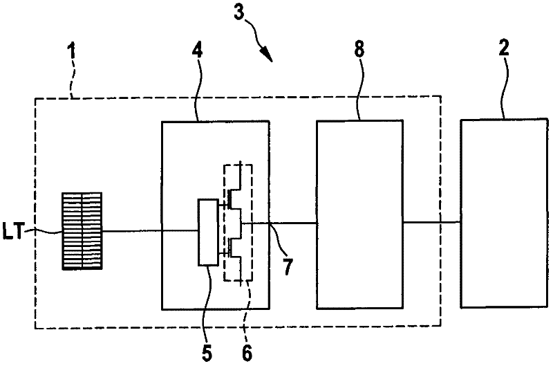
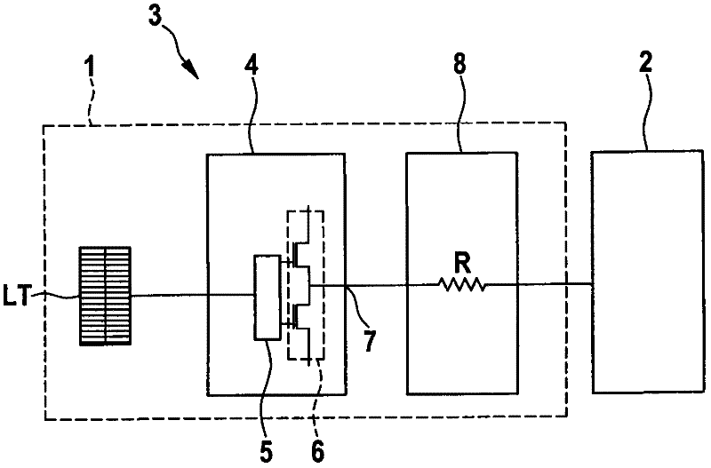
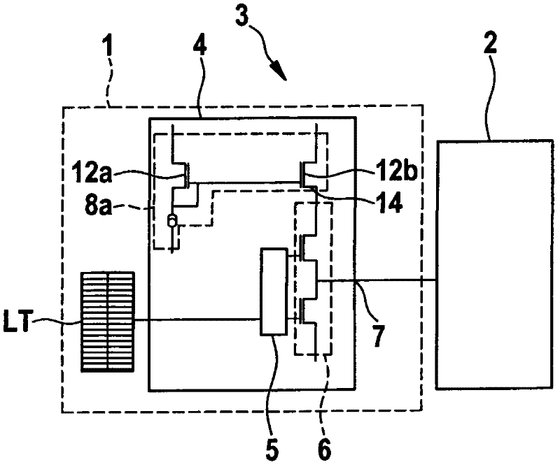
A method, actuating device, and microsystem device are described for controlling a micromechanical actuator, which has a rechargeable capacitor for generating a mechanical motion of the micromechanical actuator, a memory having a lookup table containing previously computed data of signal shapes for controlling the micromechanical actuator, and a driver circuit having a driver circuit control unit for processing the previously computed data, a power stage for generating the signal shapes, and an output for outputting the signal shapes, corresponding to previously computed data, to the micromechanical actuator's rechargeable capacitor. The micromechanical actuator has a limiting device, between the output of the driver circuit and the micromechanical actuator, which is for limiting a voltage excursion of the signal shapes output by the driver circuit, which are usable for generating the mechanical motion by recharging the micromechanical actuator's rechargeable capacitor. The micromechanical actuator's power consumption is reducible by limiting the voltage excursion.

Description

technical field [0001] The invention relates to a control device, a microsystem arrangement and a method for controlling a micromechanical actuator. Background technique [0002] In general, a microsystem, also referred to below as MEMS (Micto-Electro-Mechanical-System: microelectromechanical system), comprises one or more sensors, micromechanical actuators and the associated control electronics, which are integrated on a carrier substrate or on chip. The integrated control electronics generally use either linear drives (Linear-Treiber) or digital drives (Digital-Treiber). [0003] Veljko The article "Linearized Gimbal-less Two-Axis MEMS Mirrors" presented at Fiber Optic Expo & Symposium (San Diego, CA) on March 25, 2009 describes a two-axis MEMS scanning mirror that does not use a gimbaled suspension . The MEMS scanning mirror described there provides fast scanning in two axes in an angular range of up to 32° with low power consumption, wherein the MEMS scanning mirror...

Claims


Application Information

Patent Timeline
Patent Type & Authority Applications(China)
IPC IPC(8): H02N2/06
CPCH02N1/006H02N2/001B81B3/0021H02N1/00
Inventor M·L·A·迪布斯A·文茨勒
Owner ROBERT BOSCH GMBH
Why Eureka
Try Eureka