
Heat engine

A technology of heat engine and heating part, applied in hot gas variable capacity engine devices, mechanical equipment, machines/engines, etc., can solve problems such as catastrophic engine damage, avoid stall or engine damage, large adaptability, high fuel The effect of efficiency

Inactive Publication Date: 2012-05-09
UNIVERSITY OF NEWCASTLE
View PDF6 Cites 11 Cited by
  • Summary
  • Abstract
  • Description
  • Claims
  • Application Information

AI Technical Summary

Problems solved by technology

Stroke length requires high precision control so as not to cause mechanical contact between the piston and cylinder head ("overtravel"), which can cause catastrophic damage to the engine

Method used


Image

  • Heat engine
  • Heat engine
  • Heat engine

Examples


Embodiment Construction

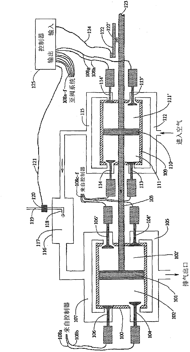
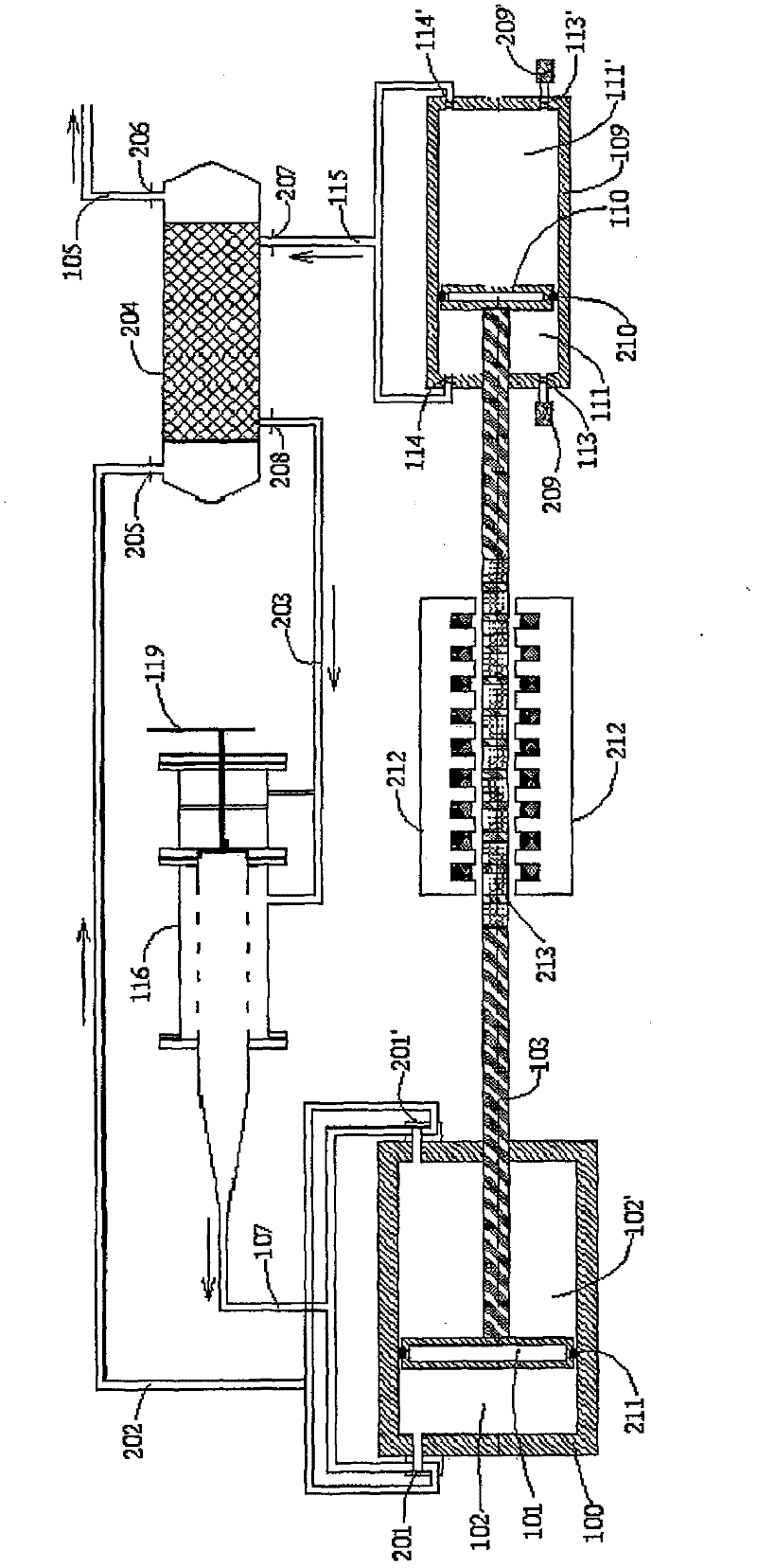
[0038] figure 1 A heat engine system according to a first embodiment of the present invention is shown. The system operates on an external combustion cycle with substantially constant pressure combustion, similar to conventional gas turbines. The compression and expansion devices consist of double-acting reciprocating cylinders arranged in a linear free-piston configuration, and the load is induced using a linear-acting load device, such as a linear generator or a hydraulic cylinder. Electronic controllers are used to control the opening and closing of cylinder valves and the rate of fuel injection.

[0039] The system comprises an expansion cylinder 100 with a reciprocating piston 101 inside. The piston 101 is sealed to the wall of the cylinder 100 by precision machining or using piston rings as is common in conventional engines, and it divides the cylinder 100 into two working chambers 102 and 102'. The piston 101 is fixed to a rod 103, and the rod 103 extends through one...


PUM


Abstract

Provided is a heat engine comprising compressor and expander displacement elements (210, 211) reciprocating in respective compression and expansion chambers (111, 111', 102, 102' ) and arranged in a linear, free-piston configuration, a combustor (116) separate from the compression and expansion chambers (111, 111', 102, 102' ), and a linear energy conversion device (212, 213) providing conversion of solid, liquid, or gaseous fuel into hydraulic, electric, or pneumatic energy by means of subjecting a working fluid to a thermodynamic cycle with substantially constant pressure combustion. The inlet and outlet valves of the compression chamber (102, 102') and the rate of fuel injection to the combustor (116) are actively controlled by an electronic controller to avoid engine damage, and to maintain thermodynamic efficiency over a wide range of loads.

Description

technical field [0001] The invention relates to a heat engine. Background technique [0002] Researchers and engineers have been concerned with the efficient conversion of heat to mechanical work for more than a century, and recent years have seen an increased focus on pollutant emissions from power generation. While internal combustion engines provide excellent fuel conversion efficiency in many situations, external combustion engines have an unrivaled performance in terms of exhaust emission levels, mainly due to significantly lower combustion temperatures. Exhaust gas components generally recognized as harmful to human health, such as nitrogen oxides, carbon monoxide and particulate matter, are increasingly being regulated by governments around the world, especially in densely populated areas. Having an external combustion engine that can compete with the fuel efficiency of an internal combustion engine would be of great interest due to understandable environmental benef...

Claims


Application Information

Patent Timeline
IPC IPC(8): F02G1/02
CPCF02G1/02F02G3/02
Inventor 里卡德·米凯尔森安东尼·保罗·罗斯基利
Owner UNIVERSITY OF NEWCASTLE
Learn More