Circuit and method used for improving dynamic response speed of PFC (power factor correction)

A dynamic response, circuit technology, applied in the direction of high-efficiency power electronic conversion, electrical components, output power conversion devices, etc., can solve the problems of large influence of diode conduction threshold, slow action time, large dispersion, etc., to improve dynamic Response speed, accurate dynamic adjustment point, small discrete effect

Active Publication Date: 2012-05-16
INVENTRONICS HANGZHOU
View PDF6 Cites 10 Cited by
  • Summary
  • Abstract
  • Description
  • Claims
  • Application Information

AI Technical Summary

Problems solved by technology

[0008] but figure 2 The voltage dynamic adjustment circuit shown has the following disadvantages: the operating voltage of the voltage dynamic adjustment circuit is jointly determined by the conduction threshold of the diode and the reference voltage of the voltage loop, and the conduction threshold of the diode is greatly affected by the outside world, such as temperature drift, Factors such as the size of the on-state current will eventually cause the action time of the voltage dynamic adjustment circuit to be difficult to determine, resulting in greater dispersion
For example, when the PFC circuit is working in a steady state, the voltage dynamic adjustment circuit may also operate; or when it is dynamic, the action time is too slow

Method used


Image

  • Circuit and method used for improving dynamic response speed of PFC (power factor correction)
  • Circuit and method used for improving dynamic response speed of PFC (power factor correction)
  • Circuit and method used for improving dynamic response speed of PFC (power factor correction)

Examples


Embodiment Construction

[0034] In order to make the above objects, features and advantages of the present invention more comprehensible, specific implementations of the present invention will be described in detail below in conjunction with the accompanying drawings.

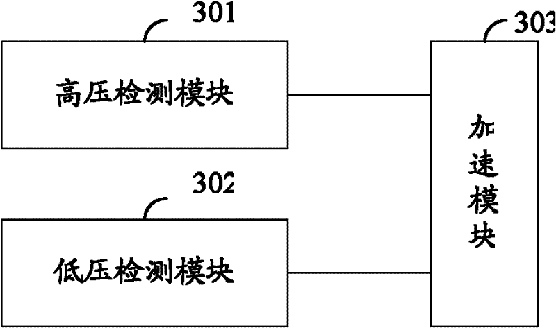
[0035] see image 3 , which is a schematic diagram of a circuit for improving the dynamic response speed of a PFC circuit provided by the present invention.

[0036] The circuit for improving the dynamic response speed of the PFC circuit provided by the present invention includes: a high voltage detection module 301, a low voltage detection module 302 and an acceleration module 303;

[0037] The high-voltage detection module 301 is configured to trigger the conduction of the acceleration module 303 when detecting that the maximum value of the PFC bus output voltage is greater than a predetermined upper limit;

[0038] It should be noted that the maximum value of the output voltage of the PFC bus can be detected by detecting a voltage ...


PUM


Abstract

The invention provides a circuit and a method used for improving dynamic response speed of a PFC (power factor correction). The circuit comprises a high-pressure detecting module, a low-pressure detecting module, and an acceleration module, wherein the high-pressure detecting module is used for triggering the acceleration module to conduct when the maximum value of output voltage of a PFC bus is detected to be greater than a preset upper limit value; the low-pressure detecting module is used for triggering the acceleration module to conduct when the minimum value of the output voltage of the PFC bus is detected to be less than a prearrangement lower limit value; the acceleration module comprises a speed-up capacitor and an acceleration resistance connected in series; and the acceleration module is connected between an output end of the output voltage of the PFC bus and a feedback signal end of a voltage ring in a PFC control circuit, and is used for increasing a pole and a zero point for voltage; when the output voltage of the PFC bus is overpressured or undervoltage, and the circuit can trigger the acceleration module to conduct so as to act on the voltage ring to accelerate the response speed of a loop circuit. The circuit and the method provided by the invention can promote dynamic properties, meanwhile, an operating mode of a main circuit in steady state can not be influenced, and a dynamic adjusting point is accurately set and the discreteness is small.

Description

technical field [0001] The invention relates to the technical field of power factor correction (PFC, Power factor correction) circuits, in particular to a circuit and method for improving the dynamic response speed of a PFC circuit. Background technique [0002] Generally, when the PFC circuit performs voltage stabilization control, in order to achieve a high power factor, the cutoff frequency of the bandwidth of the voltage loop is generally lower than the AC power grid frequency (50 Hz or 60 Hz). [0003] see figure 1 , which is a control block diagram of a PFC main circuit topology in the prior art. [0004] figure 1 The PFC main circuit shown is a Boost circuit. The output voltage of the PFC bus acts on the voltage loop 101 through a feedback circuit composed of resistors R1 and R2. After the output signal of the voltage loop 101 is multiplied by the input voltage Vdc, it is used as a reference signal of the current comparator 102 . The output signal of the current ...

Claims


Application Information

Patent Timeline
IPC IPC(8): H02M1/42
CPCY02B70/126Y02B70/10Y02P80/10
Inventor 徐迎春葛良安邵杨钧
Owner INVENTRONICS HANGZHOU
Why Eureka
Try Eureka