Braking device of toothed solid chain type engine

A technology of engine braking and fixed chain, which is applied in the direction of engine components, machines/engines, valve devices, etc., can solve the problems of increased engine height and manufacturing cost, large hydraulic deformation, slow braking response, etc., and meet the reduction requirements , Simplify the design and reduce the cost

Active Publication Date: 2012-05-30
SHANGHAI UNIVERSOON AUTOPARTS CO LTD
View PDF5 Cites 9 Cited by
  • Summary
  • Abstract
  • Description
  • Claims
  • Application Information

AI Technical Summary

Problems solved by technology

[0006] The object of the present invention is to provide a toothed fixed chain type engine braking device, said this toothed fixed chain type engine braking device will solve t

Method used


Image

  • Braking device of toothed solid chain type engine
  • Braking device of toothed solid chain type engine
  • Braking device of toothed solid chain type engine

Examples


Embodiment 1

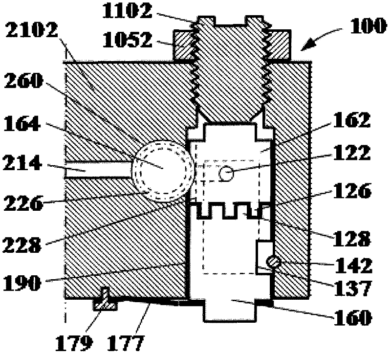
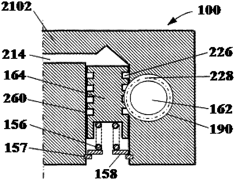
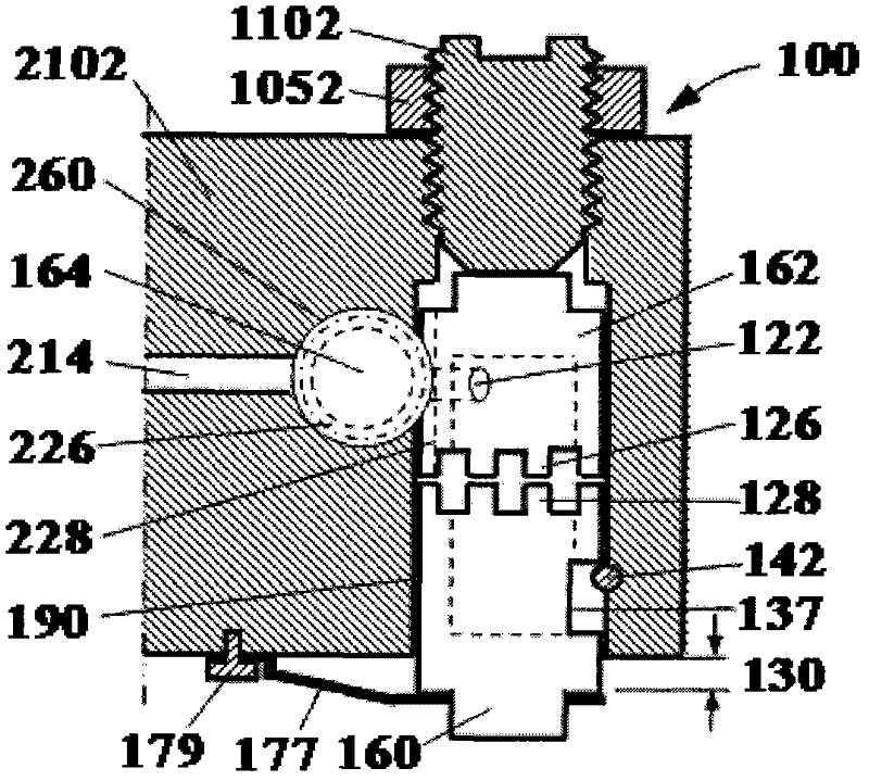
[0035] Such as figure 1 , figure 2 , image 3 , Figure 4 , Figure 5 , Image 6 with Figure 9 shown. figure 1 with figure 2 They are respectively a side view and a top view of the first embodiment of the engine braking device of the present invention when it is in the "off" position. The brake device 100 is placed in a brake box 2102, and is composed of a first plunger 160 and a second plunger 162 (braking plunger) in the vertical plunger hole 190, and a plunger rotation drive mechanism. The plunger rotary drive mechanism includes a drive piston 164 positioned in a horizontal piston bore 260, which is normally pushed by a return spring 156 (eg figure 2), stop at one side of the oil supply hole 214. The return spring 156 is located on the spring seat 158 ​​, and the spring seat 158 ​​is positioned by the retaining ring 157 fixed on the brake case 2102 . The drive piston 164 and the first plunger 162 form a translational and variable-rotation mechanism. The drive ...

Embodiment 2

[0046] Such as Figure 7 with Figure 8 as shown, Figure 7 with Figure 8 It is a top view of the second embodiment of the engine braking device of the present invention in the "off" and "on" positions. The working principle of this embodiment is basically the same as that of the first embodiment, and the difference lies in the plunger rotation drive mechanism of translation and rotation. The driving tooth 226 on the driving piston 164 in the first embodiment becomes the driving groove 2263 in this embodiment; the driven tooth 228 on the first plunger 162 becomes the driven pin 2283 in this embodiment. The reciprocating movement of the driving piston 164 in the horizontal piston hole 260 makes the first plunger 162 rotate back and forth in the plunger hole 190 through the driving groove 2263 on the driving piston 164 and the follower pin 2283 on the first plunger 162 .


PUM


Abstract

The invention discloses a braking device of a toothed solid chain type engine, and the braking device comprises a first plunger piston and a second plunger piston arranged in vertical plunger piston holes, and a plunger piston rotation driving mechanism. The lower end surface of the first plunger piston and the upper end surface of the second plunger piston are respectively provided with a tooth surface; the tooth surfaces are matched with each other; a matching non-operating position and an operating position exist between teeth of the two matched tooth surfaces; at the non-operating position, tooth crests of teeth of the first plunger piston are aligned with tooth roots of teeth of the second plunger piston; at the operating position, the tooth crests of the teeth of the first plunger piston are aligned with tooth crests of the teeth of the second plunger piston; and the plunger piston rotation driving mechanism enables the two matched tooth surfaces of the two plunger pistons to rotate between the non-operating position and the operating position. By using the braking device of the toothed solid chain type engine, the height, the volume and the weight of the engine cannot be increased or can be increased less; the design is simplified; the cost is decreased; the braking response time is reduced; the solid chain interlinkage is adopted; the lifting of a braking valve can adopt a smaller value; and the requirements on a gap of a piston and an air valve of the engine can be decreased.

Description

Technical field: [0001] The invention relates to the field of machinery, in particular to the field of vehicle engine braking, in particular to a tooth-shaped fixed-chain engine braking device. Background technique: [0002] In the prior art, the method of using the internal combustion engine as a braking means is well known, and only the engine needs to be temporarily converted into a compressor. The fuel is cut off during the conversion process, and the exhaust valve is opened at or near the end of the engine piston compression stroke to allow the compressed gas (air during braking) to be released. The energy absorbed by the engine during the compression stroke cannot be The subsequent expansion stroke returns to the engine piston, but is dissipated through the engine's exhaust and cooling system. The end result is effective engine braking that slows the vehicle. [0003] A precedent for an engine braking device is disclosed in US Patent No. 3,220,392 to Cummins, an engi...

Claims


Application Information

Patent Timeline
IPC IPC(8): F01L13/06F01L9/02F01L9/10
Inventor 杨洲
Owner SHANGHAI UNIVERSOON AUTOPARTS CO LTD
Why Eureka
Try Eureka