Ion implantation equipment and method thereof

An ion implantation equipment and ion implantation technology, applied in the field of ion implantation equipment, can solve the problem of high overall cost of the equipment, and achieve the effects of simple design, improved photoelectric conversion efficiency, and reduced cost

Active Publication Date: 2014-07-23
KINGSTONE SEMICONDUCTOR LIMITED COMPANY
View PDF3 Cites 0 Cited by
  • Summary
  • Abstract
  • Description
  • Claims
  • Application Information

AI Technical Summary

Problems solved by technology

[0005] The technical problem to be solved by the present invention is to overcome the defect that the introduction of semiconductor ion implantation technology to the field of solar wafer doping in the prior art will lead to excessively high overall equipment costs, and to provide a method that is especially suitable for the solar wafer doping process and Ion implantation equipment and method with greatly reduced overall equipment cost

Method used


Image

  • Ion implantation equipment and method thereof
  • Ion implantation equipment and method thereof
  • Ion implantation equipment and method thereof

Examples


Embodiment Construction

[0038] The preferred embodiments of the present invention are given below in conjunction with the accompanying drawings to describe the technical solution of the present invention in detail.

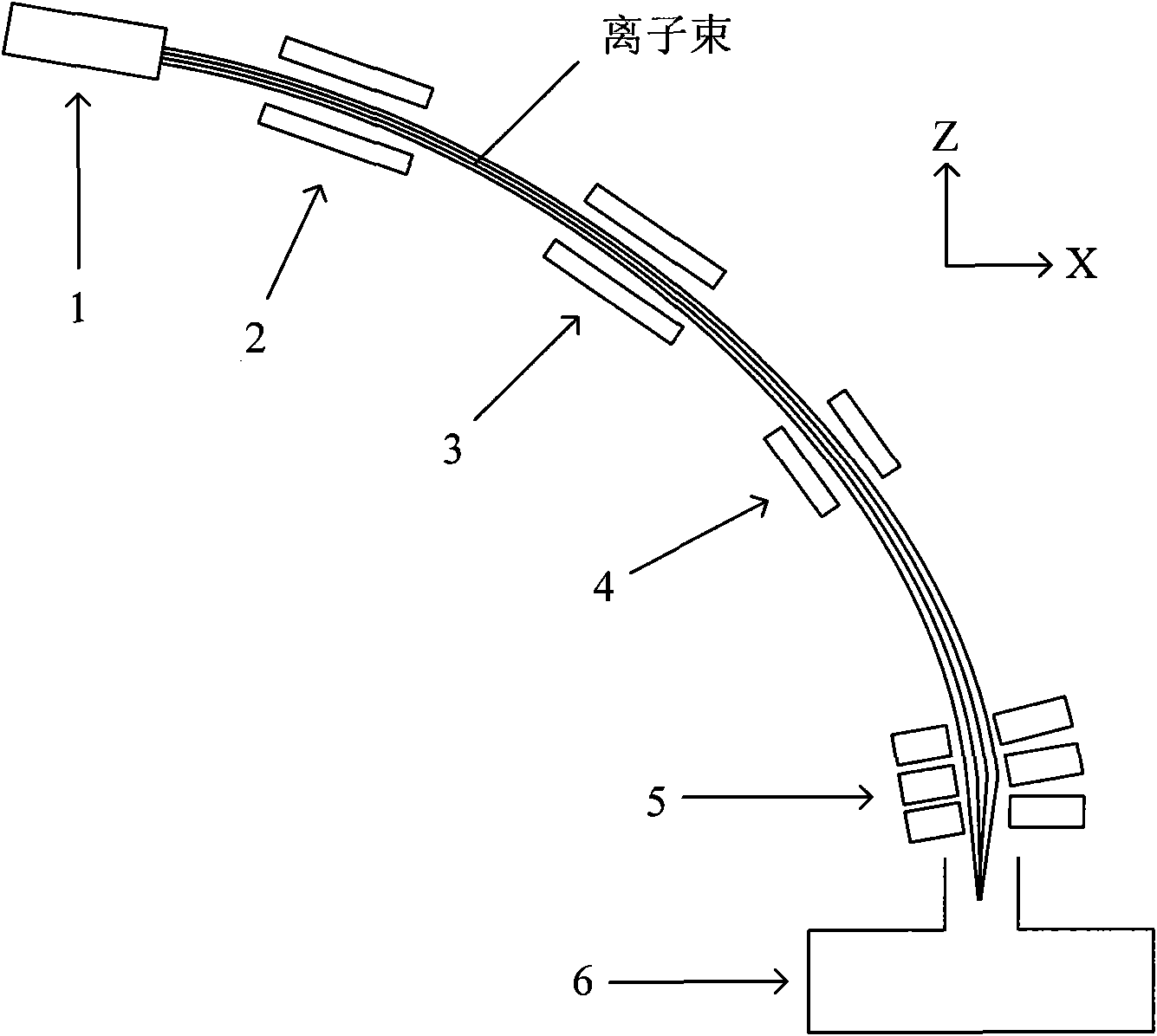
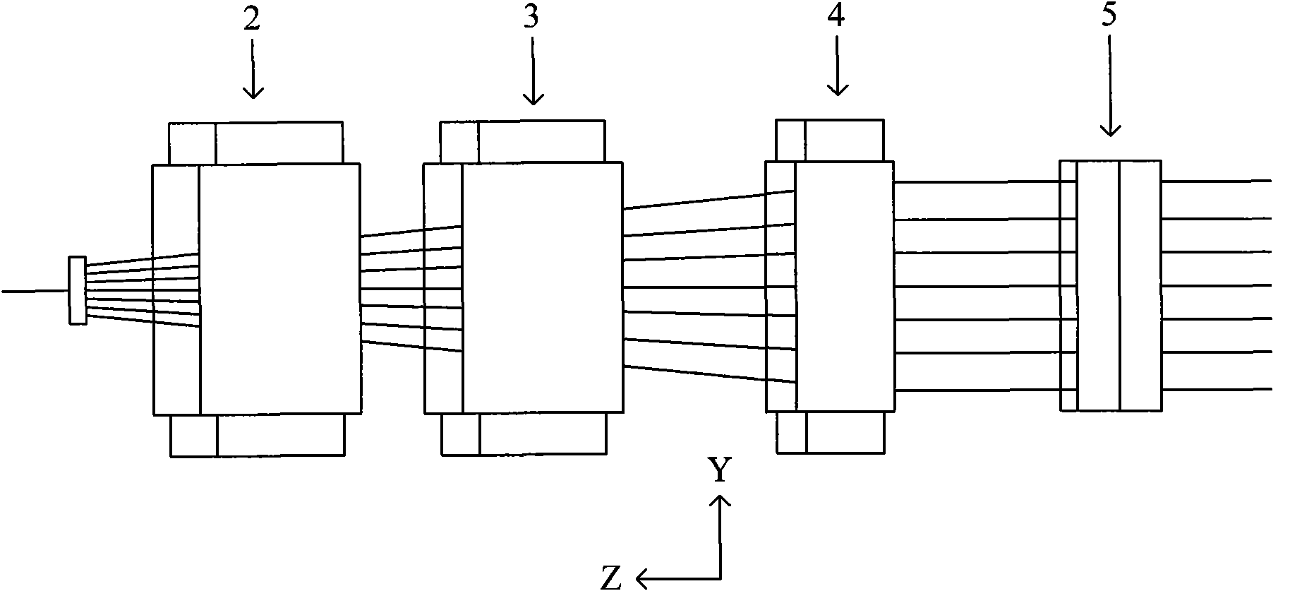
[0039] refer to figure 1 and figure 2 The ion implantation apparatus of the present invention is described, wherein figure 1 Shown is the side view of the ion implantation equipment, if the figure 1 The plane shown is defined as the X-Z plane in the three-dimensional coordinate system, then figure 2 What is shown is the projection diagram of the deflection defocus magnet, deflection magnet, deflection focus magnet and electrode system in the Y-Z plane in the ion implantation equipment.

[0040] In the ion implantation equipment, the starting point of the beam path of the ion beam is an ion source system 1, and the ion source system 1 is used to extract the ion beam required for the doping process, such as the doping process required for the solar wafer. ion beam; the end point of t...


PUM


Abstract

The invention discloses ion implantation equipment and a method thereof. In the ion implantation equipment, a beam path of an ion beam which is from an ion source system to a workpiece transmission apparatus is successively provided with: a deflection defocusing magnet, a deflection magnet, a deflection focusing magnet and an electrode system, wherein the deflection defocusing magnet is used to deflect the ion beam in a deflection plane and defocus the ion beam in a direction which is perpendicular to the deflection plane; the deflection magnet is used to deflect the ion beam in the deflection plane; the deflection focusing magnet is used to deflect the ion beam in the deflection plane and focus the ion beam in the direction which is perpendicular to the deflection plane; the electrode system is used to deflect the ion beam in the deflection plane. By using the equipment and the method of the invention, whole equipment cost can be greatly reduced and precise control of doping doses and doping uniformity can be realized.

Description

technical field [0001] The invention relates to ion implantation technology, in particular to an ion implantation device and method. Background technique [0002] New energy is one of the five most decisive technological fields in the development of the world economy in the 21st century. Among them, solar energy is a clean, efficient and inexhaustible new energy. In the new century, governments of all countries regard the utilization of solar energy resources as an important content of the national sustainable development strategy. Photovoltaic power generation has many advantages such as safety, reliability, no noise, no pollution, less constraints, low failure rate, and easy maintenance. In recent years, photovoltaic power generation technology has developed rapidly in the world, so improving the production quality and production capacity of solar wafers has become an extremely important issue. [0003] At present, in the field of solar wafer doping, the most commonly use...

Claims


Application Information

Patent Timeline
Patent Type & Authority Patents(China)
IPC IPC(8): H01J37/317H01J37/141H01L31/18
CPCY02P70/50
Inventor 陈炯钱锋
Owner KINGSTONE SEMICONDUCTOR LIMITED COMPANY
Why Eureka
Try Eureka