Mems Jetting Structure For Dense Packing

A fluid jetting, integrated circuit technology, applied in jetting device, inking device, printing, etc., can solve problems such as reducing the area of ​​bare chips

Active Publication Date: 2012-05-30
FUJIFILM DIMATIX
View PDF9 Cites 26 Cited by
  • Summary
  • Abstract
  • Description
  • Claims
  • Application Information

AI Technical Summary

Problems solved by technology

One obstacle to building smaller die is that the smaller packaging of the device reduces the area on the die available for electrical contacts

Method used


Image

  • Mems Jetting Structure For Dense Packing
  • Mems Jetting Structure For Dense Packing
  • Mems Jetting Structure For Dense Packing

Examples


Embodiment Construction

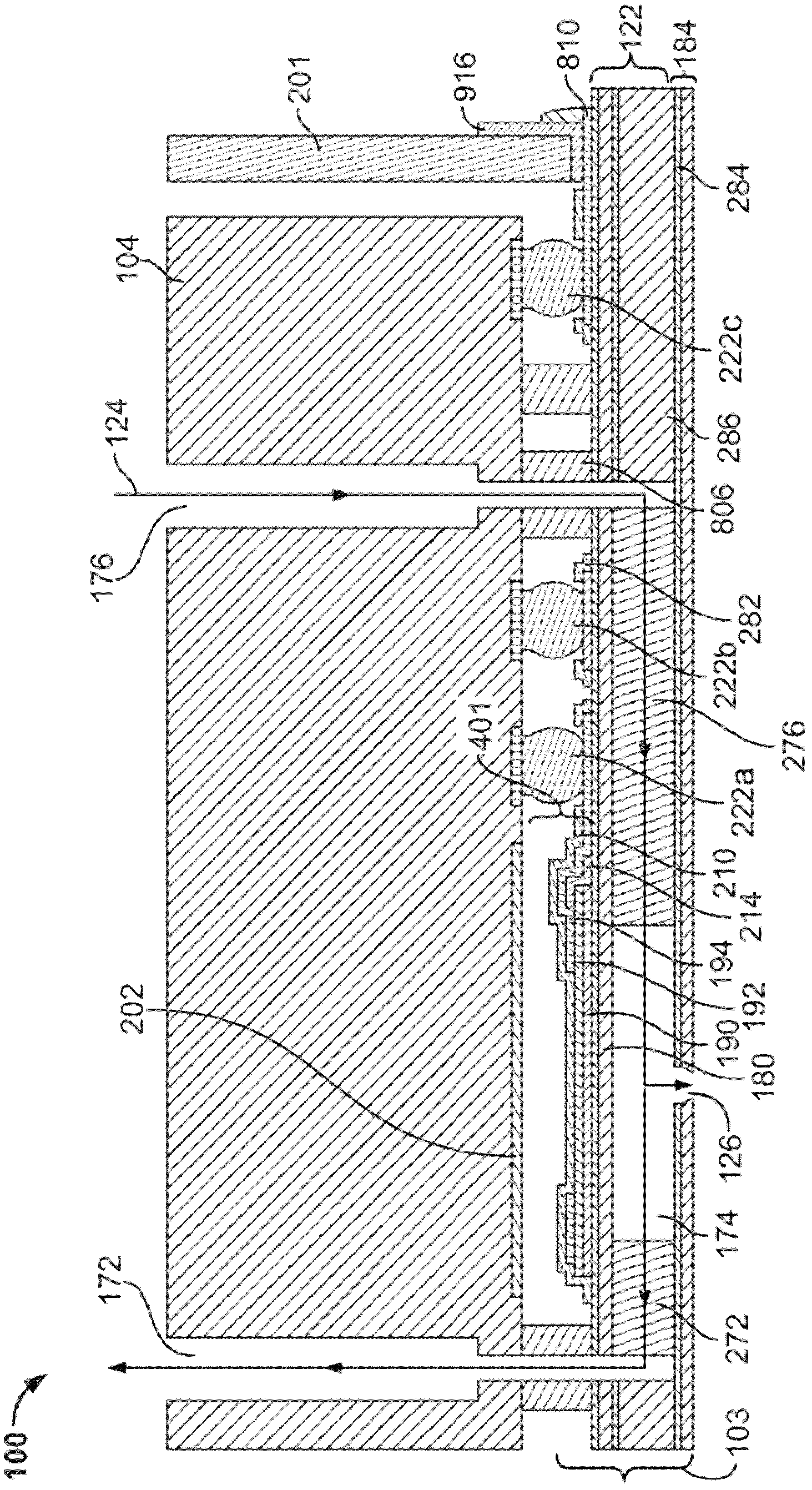
[0050] In fluid droplet ejection, such as digital inkjet printing, high speed and low cost printing are desired while avoiding inaccuracies or defects in the printed image. For example, by reducing the distance the fluid volume needs to travel from the pumping chamber to the nozzle, by having a layer separate from the die that includes the electrical connections to control the ejection of fluid from the actuators in the die, each electrical connection Low cost fluid ejectors can form high quality images at high speeds by placing the injectors adjacent to corresponding fluid ejection elements, and by including fluid inlet channels and fluid outlet channels in the housing instead of the die.

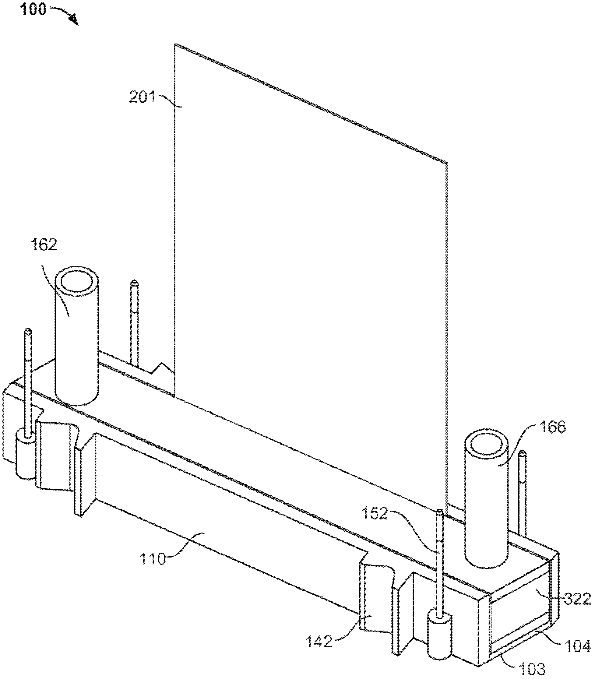
[0051] refer to figure 1 , the exemplary fluid ejector 100 includes a fluid ejection module, such as a printhead module in the shape of a quadrilateral sheet metal, which may be a die 103 fabricated using semiconductor processing techniques. The fluid ejector further includes an integrate...


PUM


Abstract

A fluid ejector includes a fluid ejection module having a substrate and a layer separate from the substrate. The substrate includes a plurality of fluid ejection elements arranged in a matrix, each fluid ejection element configured to cause a fluid to be ejected from a nozzle. The layer separate from the substrate includes a plurality of electrical connections, each electrical connection adjacent to a corresponding fluid ejection element.

Description

technical field [0001] The present disclosure generally relates to fluid ejection. Background technique [0002] Micro-electromechanical systems or micro-electromechanical systems (MEMS)-based devices can be used in a variety of applications, such as accelerometers, gyroscopes, pressure sensors or transducers, displays, optical switches, and fluid ejectors. Typically, one or more of the respective devices are formed on a single die, such as a die formed of an insulating material, a semiconducting material, or a combination of materials. The die can be processed using semiconductor processing techniques such as photolithography, deposition and etching. [0003] A fluid ejection device can have a plurality of MEMS devices each capable of ejecting fluid droplets from a nozzle onto a medium. In some devices that use mechanical actuators to eject fluid droplets, the nozzles are each fluidly connected to a flow path that includes a fluid pumping chamber. The fluid pumping chamb...

Claims


Application Information

Patent Timeline
Patent Type & Authority Applications(China)
IPC IPC(8): B41J2/14B41J2/145B41J2/175
CPCB41J2/14056B05B12/04B41J2/1404B41J2/14233B41J2002/14491B41J2002/14241B41J2202/12B41J2/14B41J2/145B41J2/175B41J2/1433
Inventor A.拜布尔E.冯埃森P.A.霍伊辛顿
Owner FUJIFILM DIMATIX
Why Eureka
Try Eureka