Monitoring apparatus for wind speed and wind direction

A wind speed and direction monitoring device technology, applied in measuring devices, fluid speed measurement, speed/acceleration/impact measurement, etc., can solve the problems of easy wear of mechanical rotating parts, test wind speed lower than actual situation, and susceptibility to lightning interference, etc. , to achieve the effects of flexible use, high practical value, and reduced adjustment costs

Inactive Publication Date: 2012-06-06
XIAN JINHE OPTICAL TECH
View PDF0 Cites 8 Cited by
  • Summary
  • Abstract
  • Description
  • Claims
  • Application Information

AI Technical Summary

Problems solved by technology

[0002] As a kind of green energy, wind power generation is strongly supported by the country. However, to ensure the normal and safe operation of wind turbines, the monitoring of wind speed and direction is an important task. The most widely used wind measuring equipment is the wind cup, wind direction Combination tester has the advantages of low cost and wide test range, but its main problem is that the mechanical rotating parts are easy to wear, the wind speed is lower than the actual situation when the wind direction is irregular, and freezing, sediment and dust may occur in severe climate areas Blockage, even fracture, and is susceptible to lightning interference and other electromagnetic wave interference; ultrasonic wind measurement technology has high precision and good performance, but it is only under research in China at present, and foreign products are expensive and difficult to popularize

Method used


Image

  • Monitoring apparatus for wind speed and wind direction
  • Monitoring apparatus for wind speed and wind direction
  • Monitoring apparatus for wind speed and wind direction

Examples


Embodiment 1

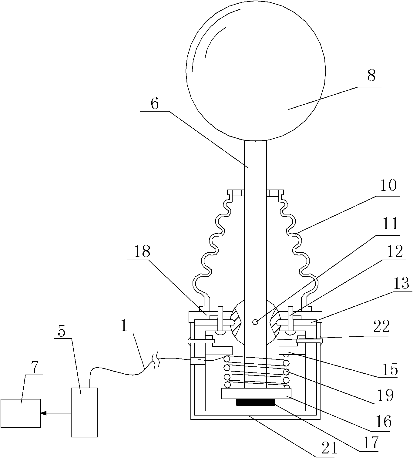
[0040] Such as figure 1 , figure 2 , image 3 with Figure 4A wind speed and direction monitoring device shown includes a support rod 6, a base 18, a rotating shaft 22, a moving plate 16, a housing 21, a test unit 5 and a processing unit 7, and the support rod 6 is arranged in the housing 21 and Protruding from the housing 21, the support rod 6 is provided with a spherical wind measuring device 8, the part of the support rod 6 protruding from the housing 21 is covered with a dust cover 8, and the bottom of the dust cover 8 is provided with Base 18, the rotating shaft 22 is installed on the housing 21 and an opening communicating up and down is provided on the rotating shaft 22, the support rod 6 can extend from the opening of the rotating shaft 22, and the rotating shaft 22 passes through the first The positioning pin 11 and the second positioning pin 13 are arranged on the base 18, preferably the first positioning pin 11 and the second positioning pin 13 are fixed on the ...

Embodiment 2

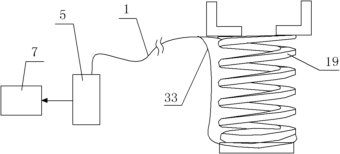
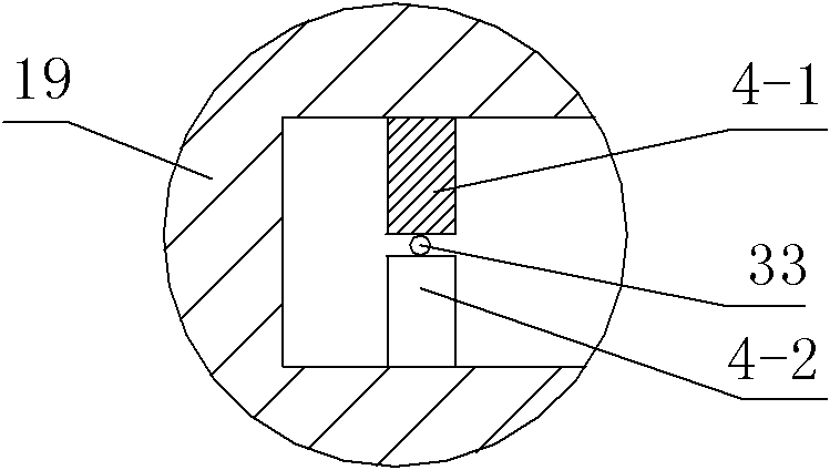
[0046] Such as Figure 5 , Image 6 As shown, in this embodiment, the difference from Embodiment 1 is that the curved support is a spring 38, and the first A-side deformed tooth 4-1 and the first B-side deformed tooth 4-2 are correspondingly arranged in the spring 38 Between two adjacent coils of spring wire, the first A-side deforming teeth 4-1 and the first B-side deforming teeth 4-2 are alternately arranged. Preferably, the spring 38 is also provided with a plurality of second A-side deformation teeth 4-3 and a plurality of second B-side deformation teeth 4-4, and a plurality of second A-side deformation teeth 4-3 and a plurality of second A-side deformation teeth 4-3 The two second B-side deformed teeth 4-4 are arranged alternately, and the second signal optical fiber 35 is sandwiched between the second A-side deformed teeth 4-3 and the second B-side deformed teeth 4-4. Two A-side deformation teeth 4-3 and the second B-side deformation teeth 4-4 are formed along the curv...

Embodiment 3

[0048] Such as Figure 7 , Figure 8 As shown, in this embodiment, the difference from Embodiment 1 is that the curved bracket is a bellows 40, and the first A-side deformation teeth 4-1 and the first B-side deformation teeth 4-2 are correspondingly arranged on the bellows On the two opposite sides of the recess on the pipe wall 42 of 40, the first A-side deforming teeth 4-1 and the first B-side deforming teeth 4-2 are alternately arranged. Preferably, the pipe wall 42 is also provided with a second A-side deformation tooth 4-3 and a second B-side deformation tooth 4-4, and the second A-side deformation tooth 4-3 and the second B-side deformation tooth 4-4 are interlaced with each other, and the second signal optical fiber 35 is clamped between the second A-side deformed tooth 4-3 and the second B-side deformed tooth 4-4, and the second A-side deformed tooth 4- 3 and the second B-side deformation tooth 4-4 along the bellows 40 every 360 degrees is a cycle, the starting point...


PUM


Abstract

The invention discloses a monitoring apparatus for a wind speed and a wind direction. The apparatus comprises a support bar, a pedestal, a rotating shaft, a movable plate, a housing, a test unit and a processing unit. The support bar is arranged in the housing and a spherical wind measurement device is arranged on the support bar. The pedestal is arranged below a dust cover. The rotating shaft is installed on the housing. The movable plate is fixed at the lower end of the support bar; a fixed plate is fixed at an inner wall of the housing; and a curve type support is arranged between the fixed plate and the movable plate. A plurality of first A side deformation gears and a plurality of first B side deformation gears are continuously laid at two opposite sides on the curve type support; and curve channels that are used for enabling one or a plurality of first signal fibers to pass are formed between heads of the plurality of first A side deformation gears and the plurality of first B side deformation gears. The test unit is connected with the first signal fibers and the processing unit is connected with the test unit. According to the apparatus provided in the invention, a fiber sensing technology is employed; and the apparatus has advantages of electromagnetic interference resistance and dustproof property and the like. Therefore, the apparatus has wide application prospects.

Description

technical field [0001] The invention relates to a monitoring device, in particular to a wind speed and direction monitoring device. Background technique [0002] As a kind of green energy, wind power generation is strongly supported by the country. However, to ensure the normal and safe operation of wind turbines, the monitoring of wind speed and direction is an important task. The most widely used wind measuring equipment is the wind cup, wind direction Combination tester has the advantages of low cost and wide test range, but its main problem is that the mechanical rotating parts are easy to wear, the wind speed is lower than the actual situation when the wind direction is irregular, and freezing, sediment and dust may occur in severe climate areas Blockage, even fracture, and are susceptible to lightning interference and other electromagnetic wave interference; ultrasonic wind measurement technology has high precision and good performance has attracted attention, but it i...

Claims


Application Information

Patent Timeline
Patent Type & Authority Applications(China)
IPC IPC(8): G01P5/26G01P13/02
Inventor 杜兵
Owner XIAN JINHE OPTICAL TECH
Why Eureka
Try Eureka