Power cable with built-in detection optical fiber

A power cable and detection optical fiber technology, which is applied to power cables with shielding layers/conductive layers, communication cables, cables, etc., can solve problems such as excessive heating of power cables, shortened life of cable insulation layers, and limited application range, etc., to achieve extended Effects of service life, increased detection distance, and increased dynamic range

Inactive Publication Date: 2012-06-06
XIAN JINHE OPTICAL TECH
View PDF0 Cites 3 Cited by
  • Summary
  • Abstract
  • Description
  • Claims
  • Application Information

AI Technical Summary

Problems solved by technology

There are two most common problems in the practical application of high-voltage power cables: 1) the load overload caused by excessive power transmission power makes the power cable heat beyond the design value; 2) the insulation layer of the power cable is damaged or Trachoma causes discharge arc and sparking phenomenon, both of which will lead to abnormal temperature rise of the power cable, the former is the temperature rise of the whole cable, and the latter is the local temperature rise of the cable, which will lead to the life of the cable insulation layer Reduced or damaged, or even fire or fire, which may cause huge damage or loss to life and property
[0003] The existing optical fiber sensing technology to monitor the abnormal temperature of power cables is mainly based on Raman backscattering temperature sensing technology and Brillouin scattering temperature and stress sensing technology. The advantages of both are distributed long-distance monitoring of power cables, and It has the advantages of anti-electromagnetic interference, etc., but the disadvantage is that the cost of equipment is high, and it cannot be applied to actual projects on a large scale, which limits the application range of monitoring equipment based on optical fiber sensing technology

Method used


Image

  • Power cable with built-in detection optical fiber
  • Power cable with built-in detection optical fiber
  • Power cable with built-in detection optical fiber

Examples


Embodiment 1

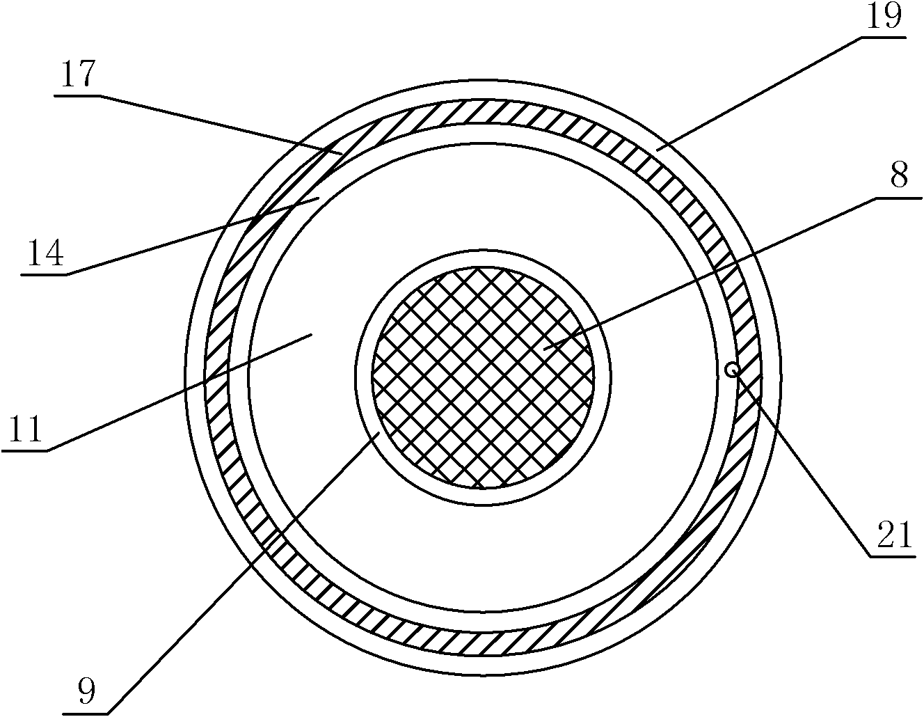
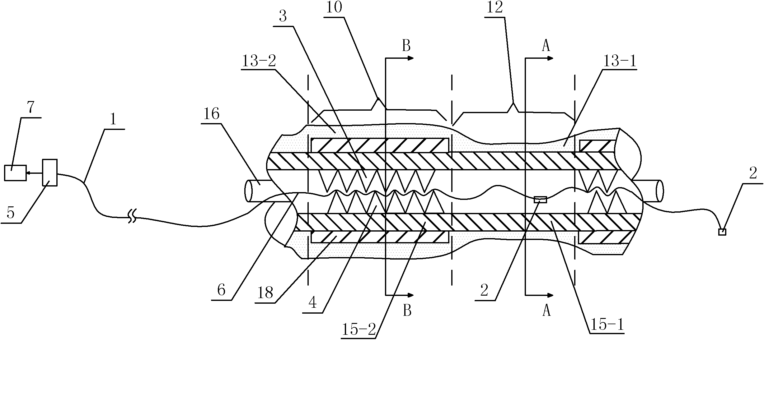
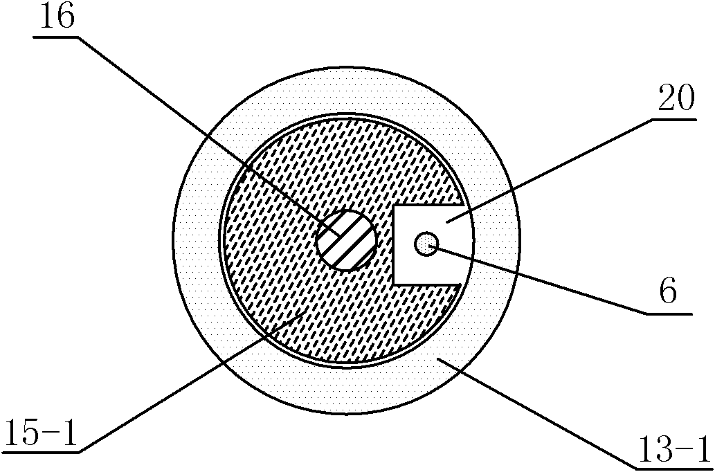
[0039] Such as figure 1 , 2 , 3 and 4 show a power cable with a built-in detection optical fiber, the conductor shielding layer 9, the insulating layer 11, the insulating shielding layer 14, the metal shielding layer 17 and the outer The outer sheath 19 is composed of at least one optical cable 21 inside the outer sheath 19. The optical cable 21 is composed of flexible segments 12 and rigid segments 10 arranged at even intervals. The flexible segment 12 and the rigid segment 10 The flexible segment 12 and the rigid segment 10 are connected with each other, and at least one signal optical fiber 6 is passed through the inside of the flexible segment 12 and the rigid segment 10. 1 is composed of a cylinder one 15-1 inside, the rigid segment 10 includes an outer sheath two 13-2 and a cylinder two 15-2 sleeved inside the outer sheath two 13-2, the cylinder one 15 -1 and cylinder two 15-2 are provided with a groove 20 inside, the signal optical fiber 6 is passed through the groove...

Embodiment 2

[0043] Such as Figure 5 As shown, in this embodiment, the difference from Embodiment 1 is that a through hole 22 is arranged in the center of the conductor 8 , and the optical cable 21 is located in the through hole 22 . In this embodiment, the structures, connections and working principles of other parts are the same as those in Embodiment 1.


PUM


Abstract

The invention discloses a power cable with a built-in detection optical fiber, and the power cable is composed of a conductor as well as a conductor shielding layer, an insulation layer, an insulation shielding layer, a metal shieling layer and an outer sheath layer which are successively arranged on the outer side of the conductor from inside to outside; at least one optical cable is arranged in the outer sheath layer; the optical cable is composed of flexible sections and hard sections, and the flexible sections and the hard sections are uniformly distributed at intervals; at least one signal optical fiber penetrates through the interiors of the flexible sections and the hard sections; each flexible section is composed of an outer sheath I and a cylinder I sheathed in the outer sheath I; each hard section comprises an outer sheath II and a cylinder II sheathed in the outer sheath II; the interiors of the cylinder I and the cylinder II are respectively provided with a groove; two opposite surfaces on the inner side of the cylinder II are respectively provided with a deformed tooth body I and a deformed tooth body II; at least one end of two ends of the signal optical fiber is connected with a test unit; and the test unit is also connected with a processing unit. The power cable with the built-in detection optical fiber has the following characteristics: simple structure design, convenience in manufacturing, low cost, flexibility in use, high sensitivity and good use effect.

Description

technical field [0001] The invention relates to a cable, in particular to a power cable with a built-in detection optical fiber. Background technique [0002] Power cables are an important part of the power transmission link. Power plants and cities now use more underground cable systems. The monitoring of underground high-voltage power cables is an important task to ensure normal power supply. basis for effective management. There are two most common problems in the practical application of high-voltage power cables: 1) the load overload caused by excessive power transmission power makes the power cable heat beyond the design value; 2) the insulation layer of the power cable is damaged or Trachoma causes discharge arc and sparking phenomenon, both of which will lead to abnormal temperature rise of the power cable, the former is the temperature rise of the whole cable, and the latter is the local temperature rise of the cable, which will lead to the life of the cable insula...

Claims


Application Information

Patent Timeline
Patent Type & Authority Applications(China)
IPC IPC(8): H01B9/02H01B11/22G02B6/44G01K11/32
Inventor 杜兵
Owner XIAN JINHE OPTICAL TECH
Why Eureka
Try Eureka