Telescopic bar distribution device for steel bar cage molding machine

A steel cage forming machine and telescopic technology, which is applied to the manufacture of ring mesh, other household appliances, household appliances, etc., can solve the problems of large floor area, high processing cost, large waste of materials and energy, etc., and achieve Small footprint, low processing cost, energy saving effect

Active Publication Date: 2012-06-13
TJK MACHINERY TIANJIN
View PDF4 Cites 17 Cited by
  • Summary
  • Abstract
  • Description
  • Claims
  • Application Information

AI Technical Summary

Problems solved by technology

[0004] The reinforcing frame device of the reinforcing cage forming machine in the prior art has the following defects: the finished product of the reinforcing cage is formed between one side of the fixed plate and the moving plate, the reinforcing frame device is fixedly connected on the other side of the fixed plate, and on both sides of the fixed plate Each is provided with a space for

Method used


Image

  • Telescopic bar distribution device for steel bar cage molding machine
  • Telescopic bar distribution device for steel bar cage molding machine
  • Telescopic bar distribution device for steel bar cage molding machine

Examples


Embodiment Construction

[0020] The implementation of the present invention will be further described below in conjunction with the accompanying drawings.

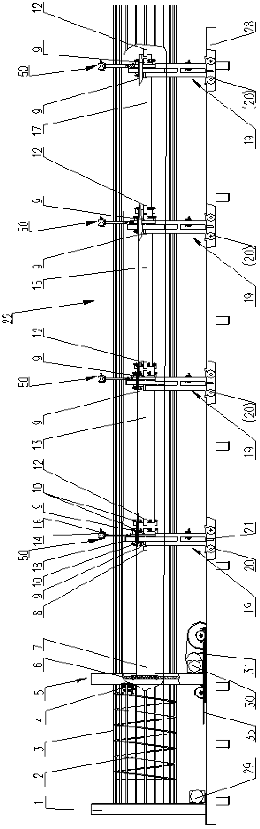
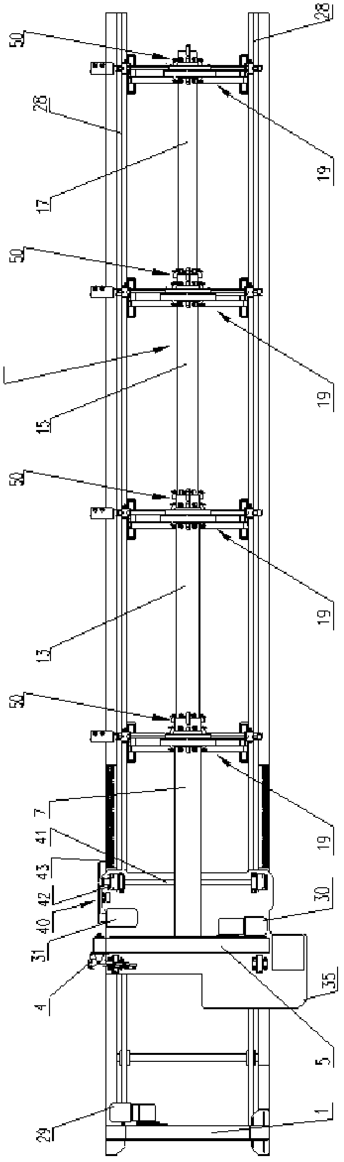
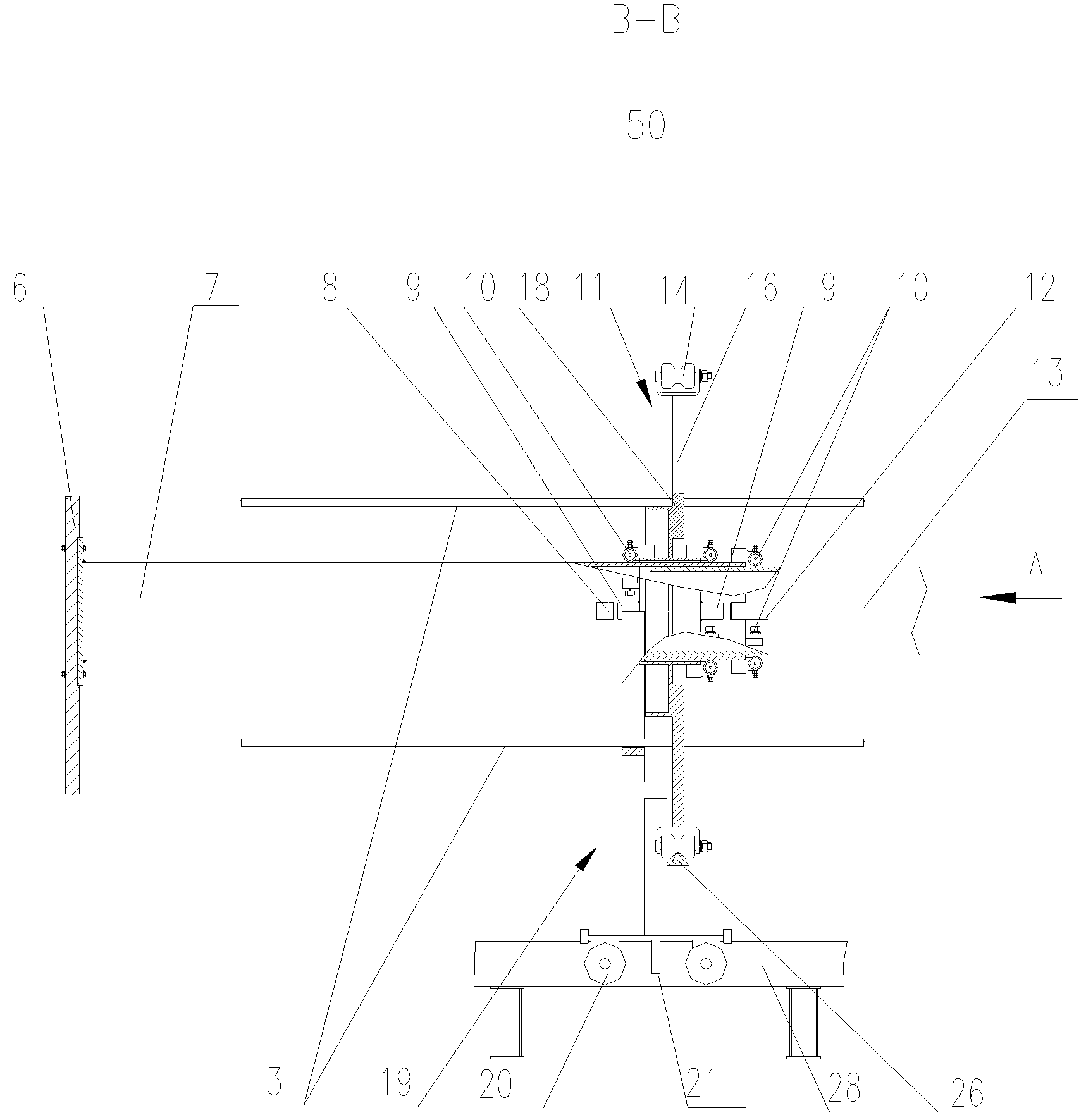
[0021] The present invention provides a telescopic reinforcement device for a steel cage forming machine. The steel cage forming machine includes a fixed plate 1 and a movable plate 5, and a rotating plate connected to a fixed plate motor 29 is provided in the fixed plate 1 (not shown in the figure) The moving plate 5 is provided with a turntable 6 that runs through and drives the main ribs 3 to rotate. The turntable 6 is connected to the moving plate rotating motor 30. The moving plate 5 moves on the bottom beam 28. The moving plate 5 and the moving device that drives it to move along the bottom beam 28 , Stirrup 2 welding devices are all fixed on the mobile plate 35; the mobile device includes: the mobile plate mobile drive unit 31 drives the mobile shaft 41 to rotate through the sprocket chain transmission mechanism 40, and the fixed walking spr...


PUM


Abstract

The invention discloses a telescopic bar distribution device for a steel bar cage molding machine. The telescopic bar distribution device comprises a turntable arranged in a mobile disk, a fixed connection pipe, a plurality of insertion pipes and a plurality of bar distribution frames, wherein one end of the fixed connection pipe is connected with the turntable; the plurality of insertion pipes which are rotated and moved along with the fixed connection pipe are sleeved and inserted into the other end of the fixed connection pipe in a sliding manner; the upper parts of the bar distribution frames are rotated along with the fixed connection pipe and the insertion pipes, and are used for supporting a main bar, and the lower parts of the bar distribution frames are supported on a floor beam in a rolling manner; and the length of the telescopic bar distribution device is gradually compressed when the mobile disk moves. The telescopic bar distribution device has the advantages that: the plurality of bar distribution rotary frames are rotated respectively along with the fixed connection pipe and the insertion pipes; a fixed stop block on the fixed connection pipe or main push stop blocks on the insertion pipes pushes or push each bar distribution frame to move along the floor beam, so that the mobile disk is rotated and welded, and compresses the length of the telescopic bar distribution device at the same time of moving along the floor beam; therefore, a steel bar cage occupies a small area, has a compact structure, is convenient to maintain, saves energy consumption, and is low in cost.

Description

technical field [0001] The invention relates to a reinforcement cage forming machine, in particular to a telescopic reinforcing device for the reinforcement cage forming machine. Background technique [0002] The reinforcement cage is formed by welding the main reinforcement and the stirrup. The main reinforcement is spaced from each other and parallel to form a column. The stirrup is wound and welded on the columnar main reinforcement according to the set pitch. The steel cage forming machine is an automatic equipment that replaces manual manufacturing of steel cages with machines. [0003] The reinforcement cage forming machine in the prior art includes: a fixed plate, a movable plate located on one side of the fixed plate, a bottom beam, and a reinforcement frame device; the fixed plate has a turntable connected to a rotating power unit; the bottom of the movable plate has a drive It is a moving device that moves along the bottom beam. There is a turntable connected to t...

Claims


Application Information

Patent Timeline
IPC IPC(8): B21F31/00
Inventor 陈振东
Owner TJK MACHINERY TIANJIN
Why Eureka
Try Eureka