Automatic pipe cutting machine

A pipe cutting machine, fully automatic technology, applied to turning equipment, turning equipment, metal processing equipment, etc., can solve the problems of unreachable dimensional accuracy, high labor intensity, waste of raw materials, etc., achieve high production efficiency, save labor, save The effect of manpower and material resources

Active Publication Date: 2016-04-20
河北松华挂车制造有限公司
View PDF6 Cites 0 Cited by
  • Summary
  • Abstract
  • Description
  • Claims
  • Application Information

AI Technical Summary

Problems solved by technology

[0002] The cutting of the long tube workpiece is generally carried out on a lathe or a grinder. When using a lathe to cut the workpiece, the long tube workpiece is clamped on the spindle chuck of the lathe and rotates with the spindle. The cutting knife is installed on the tool holder and cut with the carriage. After the cutting is completed for the first time, the cutting position of the workpiece is replaced by pushing the tail end of the workpiece. The operation is slow, the efficiency is low, the labor intensity is high, and the dimensional accuracy cannot meet the technical requirements.
And because there will be at least a section at the end of the workpiece that is as long as the main shaft, it cannot automatically enter the cutting position to complete the cutting, resulting in waste of raw materials

Method used


Image

  • Automatic pipe cutting machine
  • Automatic pipe cutting machine
  • Automatic pipe cutting machine

Examples


Embodiment Construction

[0030] Describe the present invention in detail below in conjunction with accompanying drawing:

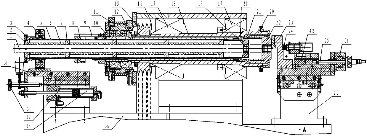
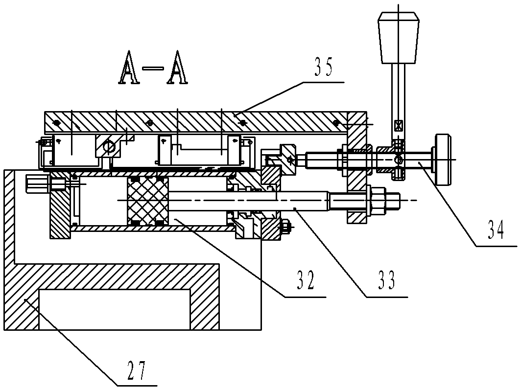
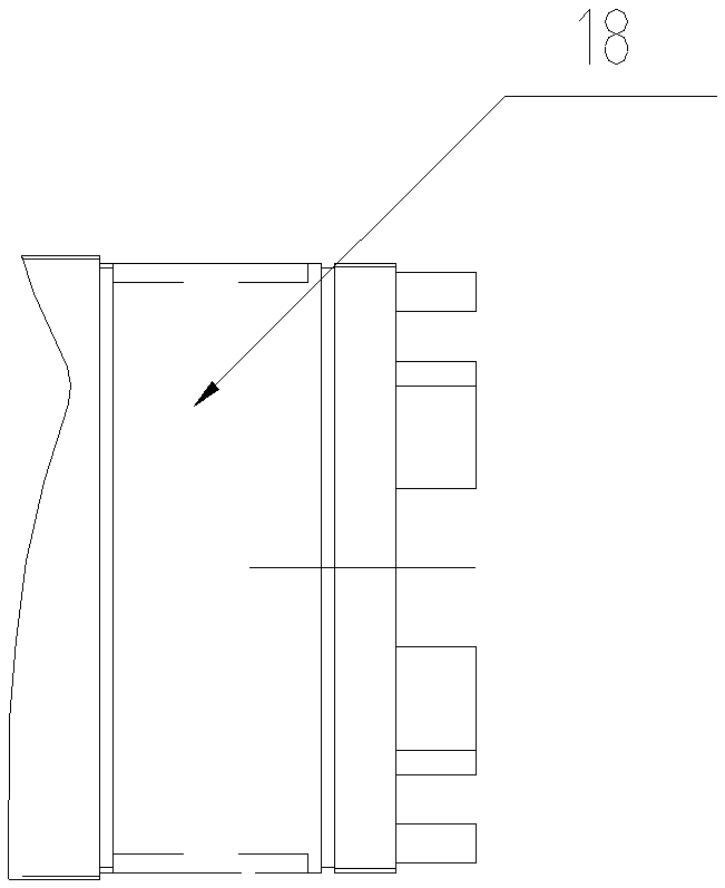
[0031] like Figure 1-2 As shown, this machine includes a hydraulic control system and an electrical control system. A headstock 16 and a tool rest seat 27 are provided on the frame seat 36. A pair of bearing seats 17 are arranged in the headstock 16, and the main shaft 18 is statically fitted in a pair of In the bearing center hole of the bearing seat 17, a passive pulley 15 is fixed on the main shaft 18; an oil pump assembly and a motor are arranged in the inner cavity of the frame seat 36, and the driven pulley 15 and the driving pulley equipped on the motor are used The wheel belts are connected; the knife rest seat 27 is provided with a left and right moving carriage 42 and a front and rear movement carriage 35, and the knife rest 23 is arranged on the left and right movement carriages 42 and the front and rear movement carriages 35, and the left and right movement carriages ...


PUM

PropertyMeasurementUnit
thicknessaaaaaaaaaa

Abstract

The invention relates to a full-automatic pipe cutter, which is characterized in that a gripping head tightly-pushing pipe is movably fitted with the inner hole of a main shaft; a feed gripping head pushing pipe is movably fitted with the inner hole of the gripping head tightly-pushing pipe, and is fixed on a feeding planker through a pushing pipe bearing seat; an feeding oil cylinder drives the feeding planker to drive the feeding gripping head pushing pipe to feed; a grip cylinder is assembled at the circumference at the left part of the gripping head tightly-pushing pipe, and drives the gripping head tightly-pushing pipe; a gripping head tightly-pushing taper sleeve pushes the gripping head to be clamped; a group of shuttling planker stroke induction switch formed by two sensors is arranged in the feeding and sliding direction of a shuttling planker of a carriage saddle; and a left-right moving planker and the shuttling planker are driven by an oil cylinder respectively. Due to the adoption of the structure, the tail section of a workpiece to be cut can be shortened to the utmost extent, the automatic feeding is achieved, manpower and material resources are saved, the operation is simple, the production efficiency is high, the machining precision is good, the time is saved. The full-automatic pipe cutter is a present pipe cutting production ideal machine.

Description

Technical field: [0001] The invention belongs to the field of metal cutting machine tools, and in particular relates to a fully automatic pipe cutting machine. Background technique [0002] The cutting of the long tube workpiece is generally carried out on a lathe or a grinder. When using a lathe to cut the workpiece, the long tube workpiece is clamped on the spindle chuck of the lathe and rotates with the spindle. The cutting knife is installed on the tool holder and cut with the carriage. After the cutting is completed for the first time, the cutting position of the workpiece is replaced by pushing the tail end of the workpiece. The operation is slow, the efficiency is low, the labor intensity is high, and the dimensional accuracy cannot meet the technical requirements. And because there will be at least a section equal to the main shaft at the tail end of the workpiece, it will not be able to automatically enter the cutting position to complete the cutting, resulting in w...

Claims


Application Information

Patent Timeline
Patent Type & Authority Patents(China)
IPC IPC(8): B23B5/14B23B15/00
Inventor 王新华
Owner 河北松华挂车制造有限公司
Why Eureka
Try Eureka