
Satellite and launch vehicle integrated aerospace system

A technology for aerospace systems and vehicles, which is applied in the field of integrated aerospace systems of satellites and vehicles, can solve problems such as difficulty in adapting to demands flexibly, constraints on the quality and capability of small-carrying spacecraft entering orbit, etc.

Active Publication Date: 2012-06-13
HARBIN INST OF TECH
View PDF2 Cites 29 Cited by
  • Summary
  • Abstract
  • Description
  • Claims
  • Application Information

AI Technical Summary

Problems solved by technology

[0004] The present invention solves the problem that it is difficult for small satellites to flexibly adapt to the requirements of different loads for emergency disaster monitoring, and the problem that the small carrying spacecraft has maximum capacity constraints in terms of the orbiting quality of the carried satellites

Method used


Image

  • Satellite and launch vehicle integrated aerospace system
  • Satellite and launch vehicle integrated aerospace system

Examples


specific Embodiment approach 1

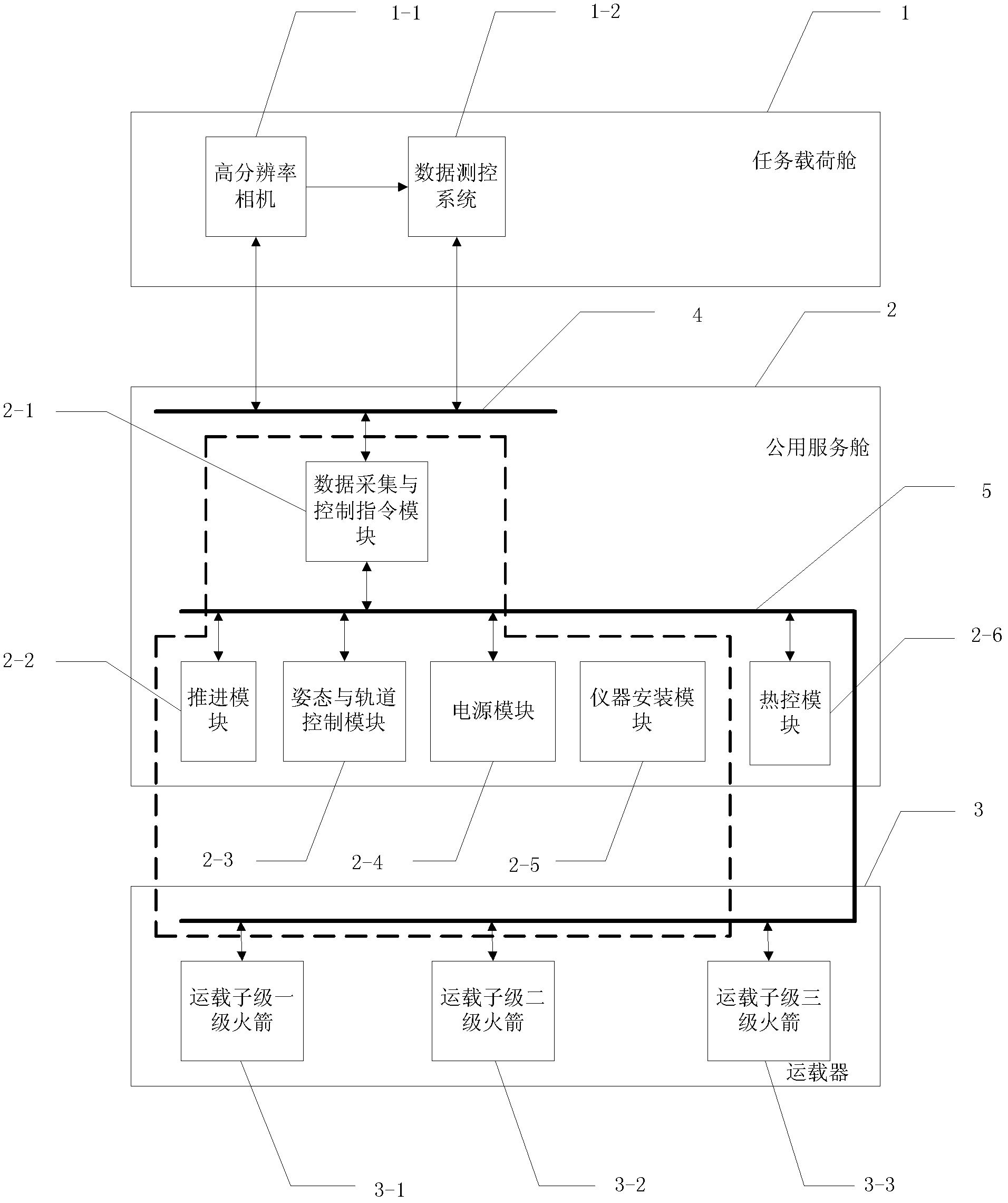
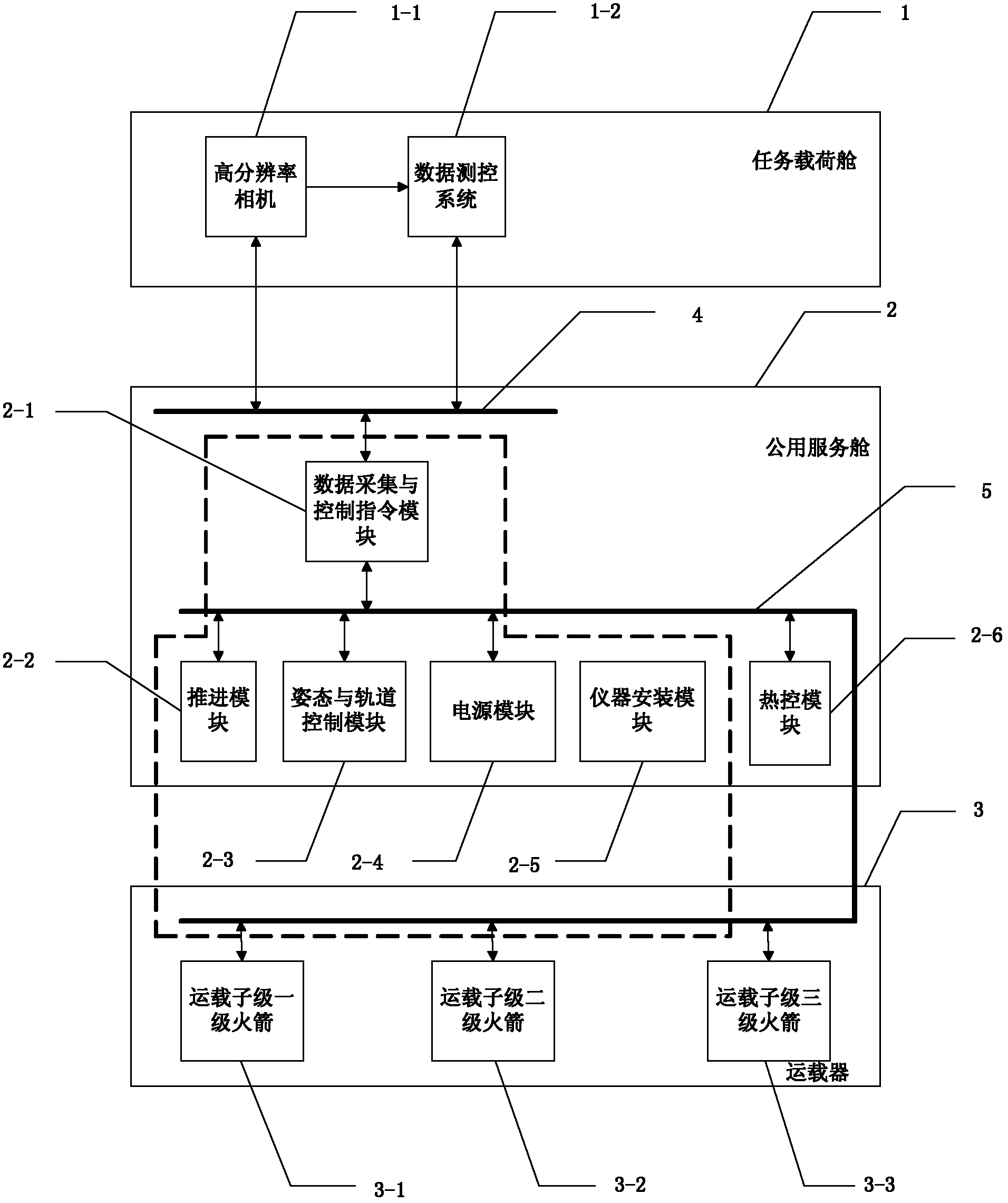
[0009] DETAILED DESCRIPTION OF THE PREFERRED EMBODIMENTS 1. An integrated aerospace system for satellites and vehicles, which includes a mission payload cabin 1 and a vehicle 3, a high-resolution camera 1-1 and a data measurement and control system 1-2 are set in the mission payload cabin 1, and the vehicle 3 includes carrier-stage first-stage rocket 3-1, carrier-stage second-stage rocket 3-2 and carrier-stage third-stage rocket 3-3, and is characterized in that: it also includes shared service module 2, first CAN bus 4 and The second CAN bus 5, data acquisition and control command module 2-1, propulsion module 2-2, attitude and track control module 2-3, power supply module 2-4, instrument installation module 2-5 and thermal control module 2-6,

[0010] The data acquisition and control instruction module 2-1 performs information transmission through the first CAN bus 4, the high-resolution camera 1-1 and the data and measurement and control module 1-2, and the data acquisition...

specific Embodiment approach 2

[0012] Embodiment 2. The difference between this embodiment and Embodiment 1 is: the propulsion module 2-2, the propulsion module used for the final boost of the vehicle 3 and the orbit maintenance and maneuvering of the satellite in orbit, the propulsion module 2-2 Provide the vehicle 3 with the control torque command required for side jet flow control in the active phase, provide propulsion power and attitude control torque commands in the final boost phase, and provide orbit maintenance and maneuver power for the satellite during the orbital operation phase control command.

specific Embodiment approach 3

[0013] Embodiment 3. The difference between this embodiment and Embodiment 1 is that the attitude and orbit control module 2-3 is a module integrated with the guidance, navigation and control of the vehicle 3 and the control of the mission load cabin 1, and adopts The three-axis stability control scheme for the ground, usually adopts the orientation mode to the sun during the orbit operation, and adopts the orientation mode to the ground when taking pictures. Expand the imaging range of high-resolution camera 1-1 for ground reconnaissance; it has high-precision and high-stability attitude control capabilities in low-orbit environments, which meets the requirements of high-resolution camera 1-1 high-resolution imaging. Attitude and orbit control module 2-3 is used to control the orbit of the common service module 2 after the first-stage rocket 3-1 of the carrier, the second-stage rocket 3-2 of the carrier and the third-stage rocket 3-3 of the carrier 3 are separated .


PUM


Abstract

The invention discloses a satellite and launch vehicle integrated aerospace system, and relates to a satellite and rocket integrated aerospace system. The system aims to solve the problems that a small satellite is difficult to flexibly adapt to the requirements of different loads of emergency disaster monitoring and that the maximum capability of a small space launch vehicle is restricted in terms of the orbit injection quality of the launched satellite. The system comprises a mission payload bay and a launch vehicle. A high-resolution camera and a data measurement and control module are arranged in the mission payload bay. The launch vehicle comprises a first-stage launch rocket, a second-stage launch rocket and a third-stage launch rocket. The system further comprises a shared service capsule and a controller area network (CAN) bus. A data acquisition and control instruction module, a propelling module, a posture and orbit control module, a power module, an apparatus mounting module and a thermal control module are arranged in the shared service capsule. The data acquisition and control instruction module controls the mission payload bay and the launch vehicle through the CAN bus. The system is applied in the field of aerospace.

Description

technical field [0001] The invention relates to an aerospace device, in particular to an integrated aerospace system of a satellite and a vehicle. Background technique [0002] After a major disaster occurs, the disaster emergency monitoring aircraft is launched, quickly deployed in space and put into use, providing accurate, real-time, high-quality disaster information data, providing a basis for disaster assessment and decision-making on disaster relief and rescue, and then implementing effective Emergency rescue and post-disaster reconstruction will minimize the loss of disasters, thereby fundamentally changing the status quo of my country's weak capabilities in natural disaster monitoring, disaster resistance, and disaster relief, and laying a solid foundation for disaster reduction and prevention. [0003] The current small satellites and small carrier spacecraft are developed for specific tasks. Due to the fixed load during the development of small satellites, it is dif...

Claims


Application Information

Patent Timeline
IPC IPC(8): G05B19/418
Inventor 张育林朱文峰曹喜滨徐国栋孙兆伟张锦绣
Owner HARBIN INST OF TECH
Learn More