Die-casting connecting method and tool for cable connector

A technology of cable joints and connection methods, which is applied in the direction of connection, circuits, electrical components, etc., can solve the problems of poor connection between cables and joints, inconvenient construction, overheating, etc., achieve beautiful and regular appearance, improve the degree of beauty, and reduce resistance rate effect

Active Publication Date: 2012-06-13
湖南湘电动力有限公司
View PDF4 Cites 2 Cited by
  • Summary
  • Abstract
  • Description
  • Claims
  • Application Information

AI Technical Summary

Problems solved by technology

When the above connection method passes tens of thousands of amperes of current, the phenomenon of sparking or overheating will occur due to poor contact of cold-pressed connection or high resistance of brazing (such as tinning, etc.) joints.
In the above connection method, when three or more cables need to be connected together, the tinning method cannot be carried out due to inconvenient construction, and at the same time, the cold-pressed connection cannot solve the problem of poor connection between the cables and the connectors

Method used


Image

  • Die-casting connecting method and tool for cable connector
  • Die-casting connecting method and tool for cable connector
  • Die-casting connecting method and tool for cable connector

Examples


Embodiment 1

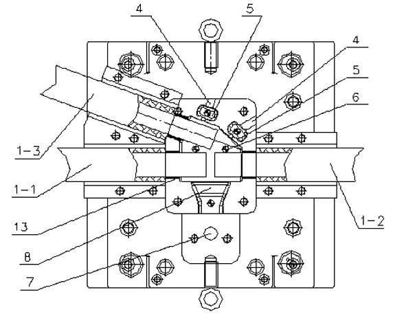
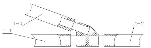
[0026] Step 1. Treatment of the cables Ⅰ1-1, Ⅱ1-2 and Ⅲ1-3 to be die-cast: cut off the rubber sleeves at the ends of the cables Ⅰ1-1, Ⅱ1-2 and Ⅲ1-3 with a knife, and cut off the rubber sleeves with copper wire The ends of cables I1-1, II1-2 and III1-3 with rubber sheaths are bound tightly and coated with a layer of paste flux.

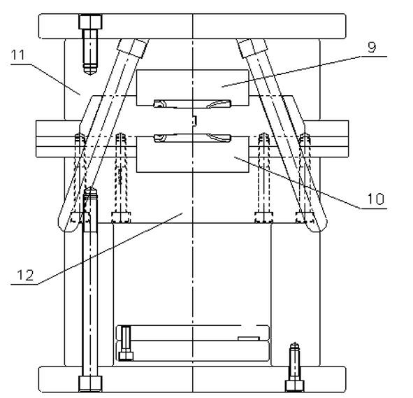
[0027] Step 2. Put the ends of the cables I1-1, II1-2 and III1-3 to be connected into the upper mold core 9 of the die-casting mold after tinning;

[0028] Step 3, pressing the upper mold core 9 of the die-casting mold on the lower mold core 10 and fixing the upper mold core 9 and the lower mold core 10 with bolts;

[0029] Step 4. Quickly press and inject the molten copper water into the die-casting mold through the sprue sleeve 7 and the inner gate 8 of the die-casting machine, and the temperature of the copper water is 1100°C--1300°C;

[0030] Step 5. During die-casting, use the external force of the die-casting head and melted copper water to remo...

Embodiment 2

[0033] Compared with Embodiment 1, only step 1 and step 2 are different, the end of cable IV2-2 is connected with the middle part of cable V2-1 to form cable joint II2, see attached Figure 4 ; Its steps 1 and 2 are:

[0034] Step 1. Treatment of the cable V2-1 and cable IV2-2 to be die-cast: cut off the rubber sheath at the end of the cable IV2-2 with a knife, tie the end of the cable IV2-2 with the rubber sheath removed and paint Apply a layer of paste flux; use a knife to cut off the rubber sheath in the middle of the cable V2-1, use copper wire to tie the middle part of the cable V2-1 with the rubber sheath removed and apply a layer of paste flux;

[0035] Step 2 is: tinning the end of the cable IV2-2 to be connected, tinning the middle part of the cable V2-1 to be connected, and putting the end of the cable IV2-2 and the middle part of the cable V2-1 into the The upper core 9 of the die-casting mould.

Embodiment 3

[0037] Compared with Example 1, only step 1 and step 2 are different, the ends of cable VI3-1 and cable VIII3-3 are connected with the middle part of cable VII3-2 to form cable joint III3, see appendix Figure 5 ; Its steps 1 and 2 are:

[0038] Step 1: Treat the cables Ⅵ3-1, Ⅷ3-3 and Ⅶ3-2 to be die-casted, cut off the rubber sheaths at the ends of the cables Ⅵ3-1 and Ⅷ3-3 with a knife, and cut off the rubber sheathed cables with copper wire Bind the ends of Ⅵ3-1 and cable Ⅷ3-3 tightly and apply a layer of paste flux; use a knife to cut off the rubber sheath in the middle of the cable Ⅶ3-2, and use a copper wire to cut off the rubber sheath in the middle of the cable Ⅶ3-2 Bind tightly and apply a layer of paste flux;

[0039] Step 2: Tin the ends of the cables VI3-1 and VIII3-3 to be connected, tin the middle of the cable VII3-2 to be connected, and tin the ends of the cables VI3-1 and VIII3-3 The middle part of the cable VII3-2 is put into the upper mold core 10 of the die-...


PUM


Abstract

The invention relates to a die-casting connecting method and a die-casting connecting tool for a cable connector. The die-casting connecting method for the cable connector comprises the following steps of: 1, processing a die-casting connecting position; 2, putting two or more cables to be connected into an upper mould of a die-casting mould after being tinned; 3, pressing a lower mould of the die-casting mould on the upper mould of the die-casting mould and firmly fixing the lower mould; 4, pressing molten copper liquid into the die-casting mould by a die-casting machine quickly; 5, exhausting air inside the die-casting mould by an external force of a die-casting head and the molten copper liquid in the die-casting process, and absorbing oxidized slag and surplus copper liquid which are generated in the die-casting process by using a residue bag; and 6, ejecting out the cable connector. The connector which is moulded by the die-casting method is high in tensile strength and attractive in appearance. The die-casting connecting tool fixes the cable required to be connected together and a circular hole formed by closing an upper mould core and a lower mould core is in interference fit with the cables, so that gas generated in the die-casting process can be effectively prevented from being exhausted from the circular hole.

Description

technical field [0001] The invention relates to a die-casting connection method and tooling for cable joints. Background technique [0002] In the power manufacturing industry, the cables that are often used are formed by wrapping dozens to hundreds of copper wires with small diameters through rubber. There are two main connection methods between cables: one is to connect two cables with a transition joint, and the cable and the joint are connected by cold pressing; the other is to use a transition joint between two cables, and the cable and the joint are connected. The joints are connected by brazing (such as tin enamel, etc.) forming method. When the above connection method passes through tens of thousands of amperes of electric current, sparking or overheating will occur due to poor contact of the cold-pressed connection or excessive resistance of the brazing (such as tinning, etc.) joint. In the above connection methods, when three or more cables need to be connected, ...

Claims


Application Information

Patent Timeline
IPC IPC(8): H01R43/02
Inventor 李再华江清波黄丁权黄泽民吕敬高
Owner 湖南湘电动力有限公司
Why Eureka
Try Eureka