Energy bus type battery equalizing circuit

A battery balancing and bus-type technology, applied in the direction of battery circuit devices, circuit devices, collectors, etc., can solve the problems of reducing the service life of the battery system, reducing solar power generation, low reliability, etc., to achieve high battery performance optimization, no Controllable effect of heat consumption and balanced current

Inactive Publication Date: 2012-06-13
JIANGSU SUMEILUN INTELLIGENT TECH
View PDF0 Cites 5 Cited by
  • Summary
  • Abstract
  • Description
  • Claims
  • Application Information

AI Technical Summary

Problems solved by technology

[0007] (1) There are many lines and complex structure, which is not conducive to standardization and modularization, and has low reliability;
[0008] (2) The problem of thermal management is prominent, not green and environmentally friendly (for energy dissipation technology);
[0009] (3) Originally, the balance requirement in the battery pack is that some batteries are deficient in energy and some have energy surplus, and the energy should be transferred from the surplus battery to the deficient battery, but in the prior art, the surplus energy is almost always replenished to Among all the batteries in the battery pack, this will reduce the service life of the battery system, and if an individual transfer method is attempted, the circuit control mechanism will be extremely complicated;
[0010] (4) The equalization current is uncontrollable or inconvenient to control, which is not conducive to adopting different equalization strengths according to the lack or surplus of different batteries, which is not conducive to battery performance optimization
[0012] For solar cells, there is also the problem of imbalance when connected in series, which directly reduces the amount of solar power generated.

Method used


Image

  • Energy bus type battery equalizing circuit
  • Energy bus type battery equalizing circuit
  • Energy bus type battery equalizing circuit

Examples


Embodiment approach

[0037] An embodiment of an energy bus type battery balancing circuit of the present invention is as follows:

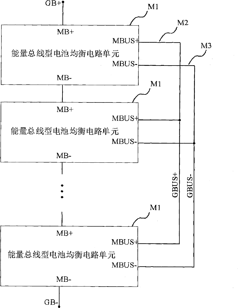
[0038] see figure 1 , is a battery system composition diagram of several energy bus type battery equalization circuit units of an energy bus type battery equalization circuit of the present invention. Such a composition is called a battery system, which is composed of an energy bus type battery equalization circuit unit M1, an energy bus positive pole M2, and an energy bus negative pole M3. Each energy bus-type battery equalization circuit unit M1 is connected in series with its battery positive pole MB+ and battery negative pole MB- end-to-end, and the total voltage obtained is the voltage of the battery system. The total voltage is equal to the sum of the battery voltages of each energy bus type battery balancing circuit unit M1. At the same time, the positive electrode MBUS+ and the negative electrode MBUS- of the energy bus of each energy bus type battery balanc...


PUM


Abstract

Disclosed is an energy bus type battery equalizing circuit. A battery system comprises a plurality of energy bus type battery equalizing circuit units by means of series connection of anodes and cathodes and parallel connection of energy bus ports, and each energy bus type battery equalizing circuit unit comprises a rechargeable battery, an embedded processing module, an energy controllable transceiving circuit, an isolated pulse transformer and the like. The energy bus type battery equalizing circuit has the advantages that the circuit is fewer in lines, simple in structure, high in reliability and extremely beneficial to standardization, energy of any batteries with surplus energy in a battery pack can be directly transferred to batteries insufficient in energy, and different equalizing intensities can be realized according to insufficient or surplus degrees of different batteries, so that high-efficiency equalization and performance optimization of the batteries are realized. The energy bus type battery equalizing circuit fundamentally solves the problem of grouping application of power batteries, super capacitors, solar batteries and the like and is suitable for large-scale industrialized production, and popularization of electric vehicles, hybrid electric vehicles, solar power stations and the like is greatly promoted.

Description

technical field [0001] The invention relates to a rechargeable battery and its management system. Background technique [0002] There is no doubt that electric vehicles and electric bicycles will become the development direction of the next generation of vehicles due to their absolute advantages of zero emission and environmental protection. Whether it is the above-mentioned pure electric vehicles or hybrid vehicles, high requirements are placed on reusable rechargeable power batteries. [0003] It can be seen from indicators such as battery capacity, lifespan, and energy density that lithium-ion power batteries have become the first choice for power batteries for next-generation electric vehicles, but this kind of battery has a development bottleneck. [0004] Because the voltage of each single battery is very low (only within a few volts), multiple single batteries must be connected in series to reach tens of volts to hundreds of volts when used in electric vehicles. And...

Claims


Application Information

Patent Timeline
Patent Type & Authority Applications(China)
IPC IPC(8): H02J7/00
Inventor 张恩迪许志许春香
Owner JIANGSU SUMEILUN INTELLIGENT TECH
Why Eureka
Try Eureka