Self-correction area array source visual field measuring instrument

A field of vision and array source technology, applied in the field of perimeter, can solve problems such as difficult maintenance, limited application programs, misjudgment, etc., and achieve the effect of solving aging problems, prolonging service life, and flexible and convenient operation.

Inactive Publication Date: 2012-06-20
BEIJING UNIV OF TECH
View PDF6 Cites 5 Cited by
  • Summary
  • Abstract
  • Description
  • Claims
  • Application Information

AI Technical Summary

Problems solved by technology

[0002] The visual mark of the traditional hemispherical perimetry is displayed by means of light-emitting diodes or optical fibers embedded in the hemispherical screen, or light point projection. This display method has great limitations, because not only the size of the visual mark, but also the The position, color and shape are relatively fixed, which limits the implementation of many applications, and the optical system for displaying the visual target is more complicated and difficult to maintain. For example, the position and size of the visual target of the fiber-optic automatic vision instrument are fixed by the position and size of the optical fiber hole ; Light-emitting diode as a display visual mark not only cannot be flexibly converted

Method used


Image

  • Self-correction area array source visual field measuring instrument
  • Self-correction area array source visual field measuring instrument
  • Self-correction area array source visual field measuring instrument

Examples


Example Embodiment

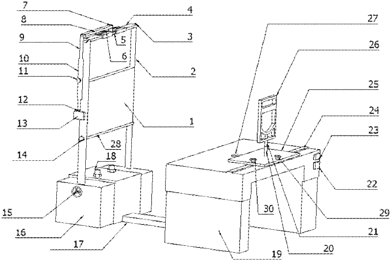
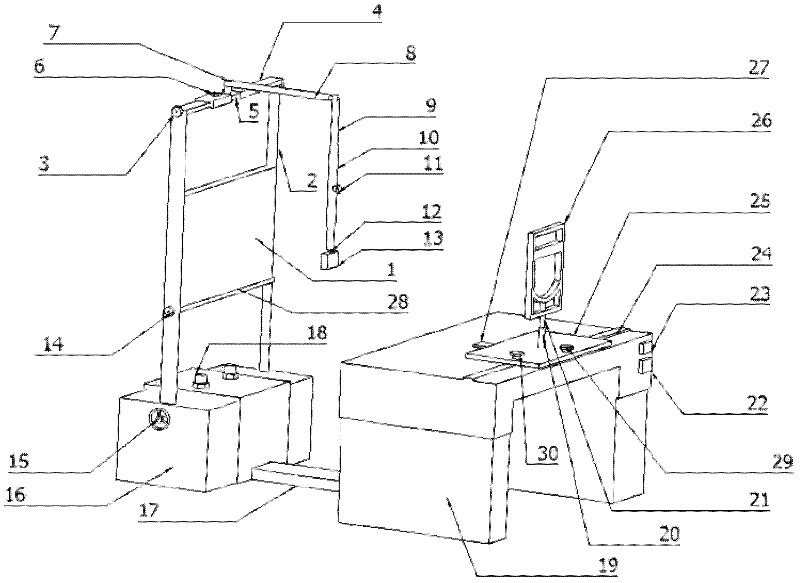
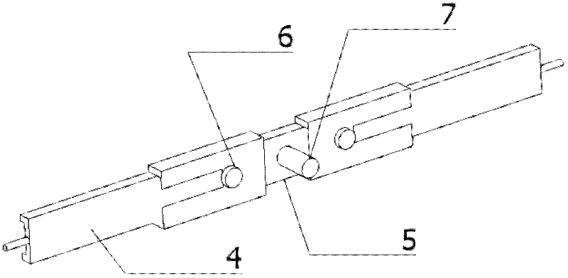
[0015] The following combines the attachment to explain the present invention in detail: figure 1 Show, the facial sources display equipment of the present invention uses a flat electronic display screen 1. For the use of a tablet electronic display screen with different length ratio, it can adjust the positioning bolt 6 on the variable long connection rod 4, eliminating or shortening or shortening The length of the variable length connection rod 4; adjust the positioning bolt 14 on the supporting part 28, the distance between the fixed support frame 2; the distance between the rotating hand wheel 15 can adjust the support frame 2. Installing support parts 28 at the bottom end of Tablet Electronic Display 1 is mainly convenient for the connection of tablet electronic display 1 and supporting frame 2. The connection between the supporting part 28 and the support frame 2 can be fixed by positioning bolt 14. The supporting rack 2 and the base 16 are connected through a fixed bol...


PUM


Abstract

The invention discloses a self-correction area array source visual field measuring instrument, and belongs to an instrument for diagnosing diseases which is generally used in ophthalmology. In the area array source display equipment provided by the invention, a flat panel electronic display screen is adopted; for the selected flat panel electronic display screen of a different aspect ratio, the length of a variable-length connecting rod can be elongated or shortened by adjusting a positioning bolt on the variable-length connecting rod; the variable-length connecting rod is connected with a variable-length straight rod; the variable-length straight rod is connected with the variable-length connecting rod; the tail end of the variable-length connecting rod is connected with image acquisition equipment; and a pedestal is connected with a lifting electric table through a slide rail and is used for placing the flat panel electronic display screen. The upper surface of the lifting electric table is provided with a horizontal guide rail which is parallel to the flat panel display screen; a sliding plate which can slide along the horizontal guide rail is arranged on the horizontal guide rail; and a vertical guide rail along which the sliding plate can vertically slide is arranged perpendicular to the horizontal guide rail. The sliding plate is connected with a lower holder through theconnecting rod and a threaded sleeve. The visual field measuring instrument is suitable to be used by different levels of hospitals, is low in cost, and flexible and convenient in operation, and has a self-maintenance function.

Description

technical field [0001] The invention relates to a perimetry instrument for measuring the visual field of a subject, which belongs to an instrument commonly used in ophthalmology for diagnosing diseases. Background technique [0002] The visual benchmark of the traditional hemisphere -type vision instrument is displayed by the light -emitting diode or optical guidance fiber or light spot projection of the hemisphere screen. The location, color and shape are relatively fixed, which limits the implementation of many applications, and the optical system of the visual benchmark is relatively complicated and difficult to maintain. ; Light-emitting diodes as a display visual standard not only cannot be flexibly converted in color, but also the brightness level is not easy to subdivide, which affects the visual field detection effect. Because the traditional hemisphere visual field adjustment center fixation point or the location, display range, size, or color of the visual benchma...

Claims


Application Information

Patent Timeline
IPC IPC(8): A61B3/00
Inventor 许东来高强强孙国芹范宗涛王晓亮刘星
Owner BEIJING UNIV OF TECH
Why Eureka
Try Eureka