
Purifier metal carrier core winding machine

A technology of metal carrier and core winding machine, which is applied in the direction of chemical instruments and methods, separation of dispersed particles, separation methods, etc., can solve the problems of large deviation in the degree of tightness of winding products, affect the quality of winding cores, and complex structures, etc., to improve production Efficiency and product quality, improved labor safety, precise core dimensions

Active Publication Date: 2014-12-24
江苏省机械研究设计院有限责任公司
View PDF4 Cites 0 Cited by
  • Summary
  • Abstract
  • Description
  • Claims
  • Application Information

AI Technical Summary

Problems solved by technology

[0002] At present, the metal carrier core rolling method is still at a relatively low level, the degree of automation is not high, and the efficiency is low.
The common structure is that the motor is directly connected to the reel, installed on a fixed stand, manually put the gear material, sheet material, and brazing material into the slit of the reel, and turn on the power of the motor. During the rolling process, manual rolling The material is gradually wound into a cylindrical shape, the size is completely controlled manually, the geometric size has a large dispersion, the identity is poor, and the degree of tightness of the wound product has a large deviation. It is necessary to manually adjust the diameter of the core after rolling, which seriously affects the quality of the core.
And the degree of automation of the rolling process is low, and the ultra-thin metal foil is very easy to hurt the operator's fingers, and the safety is poor
[0003] CN102151483A provides a fully automatic metal ternary purifier roll core device, but its structure is relatively complicated, maintenance is difficult, and the manufacturing cost is relatively high

Method used


Image

  • Purifier metal carrier core winding machine
  • Purifier metal carrier core winding machine
  • Purifier metal carrier core winding machine

Examples


Embodiment Construction

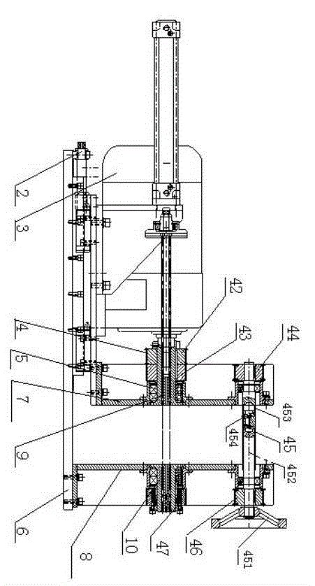
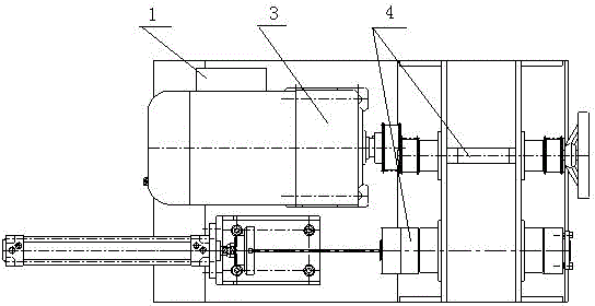
[0031] like figure 1 As shown, the present invention is mainly composed of the following parts: electrical control system 1, side baffle width adjustment device 2, motor reducer 3 providing winding power, toothed belt transmission system 4, reel system 5, and stand 6. A movable side plate 7 and a fixed side plate 8 are correspondingly arranged on the platform 6 , and the two side plates are correspondingly respectively pierced with reels that can drive the reel mandrel to wind. The fixed side plate 8 is vertically fixed on the stand 6; the movable side plate 7 can be driven by the side baffle width adjusting device 2, and moves horizontally along the stand 6 on the same central horizontal line as the fixed side plate 8.

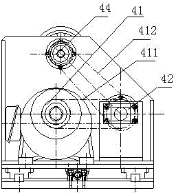
[0032] like figure 1 , figure 2As shown, the toothed belt transmission system as a whole has a π-shaped transmission structure, including three-stage transmission: the first-stage drive wheel 41 is installed on the output shaft of the motor reducer 3, and...


PUM


Abstract

The invention provides a purifier metal carrier core winding machine, which has a simple structure, is convenient to operate and can effectively guarantee the winding quality. The purifier metal carrier core winding machine comprises a rack, a transmission system, a scroll system comprising a core winding shaft, and a power source for providing winding power, wherein the rack is provided with two corresponding side plates; the two side plates are correspondingly respectively penetrated with the scroll capable of driving the core winding shaft to wind; the transmission system comprises a middle transmission shaft and a synchronous tooth-shaped belt pulley group; the middle transmission shaft is arranged between the two side plates; two ends of the middle transmission shaft are respectively connected with the synchronous tooth-shaped belt pulley group respectively arranged on two side plates in a driving mode; and the synchronous tooth-shaped belt pulley group is respectively connected with the scroll penetrated on the side plate on one side of the synchronous tooth-shaped belt pulley group in a driving mode. According to the purifier metal carrier core winding machine, the defect of seriously insufficient supporting rigidity of the winding shaft cantilever supporting structure of the traditional core winding machine is directly eliminated, the purpose that the scrolls on two sides are synchronously wound is realized, and the winding quality of the core winding product is effectively guaranteed.

Description

technical field [0001] The invention relates to rolling equipment for rolling cores of metal carriers in exhaust gas purifiers of automobiles and motorcycles. Background technique [0002] At present, the metal carrier core rolling method is still at a relatively low level, with a low degree of automation and low efficiency. The common structure is that the motor is directly connected to the reel, installed on a fixed stand, manually put the gear material, sheet material, and brazing material into the slit of the reel, and turn on the power of the motor. During the rolling process, manual rolling The material is gradually wound into a cylindrical shape, the size is completely controlled manually, the geometric size has a large dispersion, the identity is poor, and the degree of tightness of the wound product has a large deviation. It is necessary to manually adjust the diameter of the core after rolling, which seriously affects the quality of the core. . And the degree of ...

Claims


Application Information

Patent Timeline
Patent Type & Authority Patents(China)
IPC IPC(8): B01D53/94
Inventor 杨晓明魏一兵戎连杨乐
Owner 江苏省机械研究设计院有限责任公司
Learn More